2 register organization – Rockwell Automation 57C421B Pulsetach Input Module/DCS 5000/AutoMax User Manual
Page 26
4Ć4
4.2
Register Organization
The module contains registers for the pulse counter, the comparator,
the timer, module status, and module control. The register
organization is shown in figure 4.5. The following sections describe
each register in detail. A detailed memory map can be found in
Appendix G. Note that at power up, all registers are cleared (reset to
zero).
Register
Description
0
Counter Data Latch Register
1
Counter Data Latch Register
2
Counter Update Register
3
Comparator Register
4
Comparator Register
5
Interrupt Status and Control Register
6
Mode Definition Register
7
Module Status Register
Figure 4.5 Ć Pulsetach Module Register Organization
4.2.1
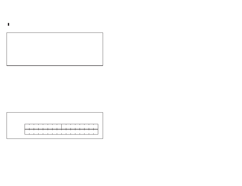
Counter Data Latch Registers (Registers 0Ć1)
Registers 0 and 1 contain a latched copy of the contents of the
module's 24Ćbit signed counter. Refer to figure 4.6.
The largest value that the counter can hold is +/- 8,388,607. This
information can be accessed by referencing registers 0 and 1 as a
long integer or as an integer by referencing register 1. Bit 7 of
register 0 is the sign bit. Bits 8 to 15 are always set to the state of bit
7. Reference the counter as an integer (register 1) if the counter
value will not exceed 32767 between readings. If the counter value
will exceed 32767, reference the counter as a long integer. These
registers are readĆonly.
0
1
2
3
4
5
6
7
9
8
10
11
12
13
14
15
Register 0
Register 1
extended sign
MS 8 bits of counter
LS 16 bits of counter
Bits
Figure 4.6 Ć Counter Data Latch Registers (Registers 0Ć1)