Rockwell Automation 57C421B Pulsetach Input Module/DCS 5000/AutoMax User Manual
Page 33
4Ć11
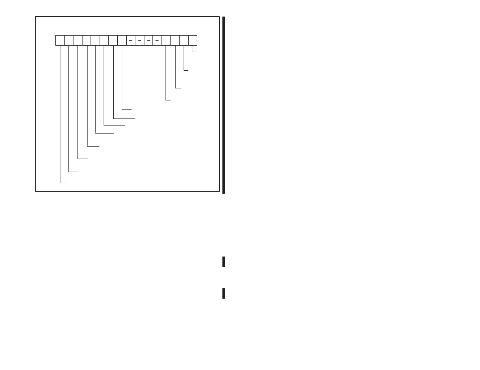
0
1
2
3
4
5
6
7
9
8
10
11
12
13
14
15
RegisĆ
ter 6
Bits
rw rw rw rw rw rw rw
rw rw rw rw
rw
External
latch
enable
External
count stop
enable
Count
reverse
Count forward
Type of pulsetach: 0 = quadrature
1 = single input
Inhibit counter
Clear/origin select
Z pulse polarity: 0 = positive logic
1 = negative logic
Count stop input select: 0 = high input
1 = low input
Origin/clear input select:
0 = high input
1 = low input
External latch input select:
0 = high input
1 = low input
Reset counter
Figure 4.10 Ć Mode Definition Register (Register 6)
4.2.6
Module Status Register (Register 7)
Register 7 contains module status and interrupt reset control bits.
Refer to figure 4.11.
Bit: 0
Description: Carry Status
This bit is set whenever acarry occurs from bit 7 of register 0
(i.e., the value of the counter has rolled over to zero in the positive
direction). This bit is reset by writing azero to register 7, bit 10.
Bit: 1
Description: Borrow Status
This bit is set whenever aborrow occurs from bit 7 of register 0
(i.e., the value of the counter has rolled over to zero in the negative
direction). This bit is reset by writing azero to register 7, bit 11.
Bit: 2
Description: Counter Greater Than Comparator
Bit 2 is set whenever the counter value (registers 0 and 1) is greater
than the comparator value (registers 3 and 4).