Rockwell Automation 57C421B Pulsetach Input Module/DCS 5000/AutoMax User Manual
Page 24
4Ć2
4.1.2
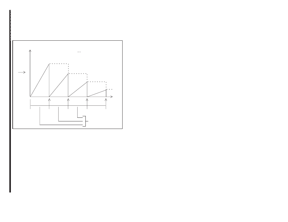
Speed Detection Mode
Speed detection mode is enabled by setting the Timer Interrupt
Enable bit (register 5, bit 5) to 1. In this mode, the counter value is
read and transferred to the latch registers each time the time period
defined in the Update Register (register 2) expires. Each time the
counter is read, the counter is reset to zero and an interrupt is
generated. The latch registers hold the latched counter value until
the counter is read again. Refer to figure 4.2.
Counter
Value
Time
Decreasing
Speed
Constant
Time Intervals
(Programmable)
Ċ Internal Counter Value
Latched Counter Value
Figure 4.2 Ć Counter Status During Speed Detection Mode
4.1.3
External Latch Mode
External latch mode is enabled by setting the Enable External Latch
Input bit (register 6, bit 0) to one. In this mode, the counter value is
read and transferred to the latch registers at the occurrence of an
external signal on the input connected to terminal 8. This signal can
be from a push button, photoĆsensor, or a similar device. Refer to
figure 4.3.
The latch registers can be programmed to be either leading
edgeĆtriggered or trailing edgeĆtriggered. The status ofregister 6, bit
14 (External Latch Input Select) defines when the external latch input
is considered to be true. The counter is not automatically reset when
it is read. To generate an interrupt when the counter is read, the
External Latch Interrupt Enable bit (register 5, bit 8) must be set to
one.