Rockwell Automation 57C421B Pulsetach Input Module/DCS 5000/AutoMax User Manual
Page 27
4Ć5
4.2.2
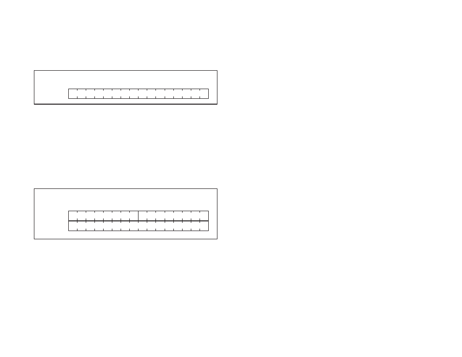
Counter Update Register (Register 2)
Register 2 contains the update period for reading the counter and
updating the latch registers. Refer to figure 4.7. The update period is
equal to the value in register 2 plus one. Each count in this register
is equivalent to 500 microseconds. For example, if you want data
latched every 22 msec., assign register 2 a value of 43 ([22 msec/.5
msec] - 1 = 43). The update period may range from 500
microseconds to 32.768 seconds. This register is read/write and is
enabled whenever bit 5, of register 5 (Timer Interrupt Enable), is set.
0
1
2
3
4
5
6
7
9
8
10
11
12
13
14
15
Register 2
update period
Bits
Figure 4.7 Ć Counter Update Register (Register 2)
4.2.3
Comparator Registers (Registers 3Ć4)
Registers 3 and 4 contain a 24Ćbit signed comparator. Refer to
figure 4.8. Bit 7 of register 3 is the sign bit. Bits 8 to 15 are always
set to the state of bit 7. The largest value that can be stored in the
comparator is +/- 8,388,607.
This information can be accessed by referencing registers 3 and 4
as a long integer or as a simple integer by referencing register 4. If
the comparator is referenced as a simple integer, it can contain only
positive numbers less than or equal to 32767. This register is
read/write.
0
1
2
3
4
5
6
7
9
8
10
11
12
13
14
15
Register 3
Register 4
extended sign
MS 8 bits of comparator
LS 16 bits of comparator
Bits
Figure 4.8 Ć Comparator Registers (Registers 3Ć4)