Rockwell Automation 57C421B Pulsetach Input Module/DCS 5000/AutoMax User Manual
Page 16
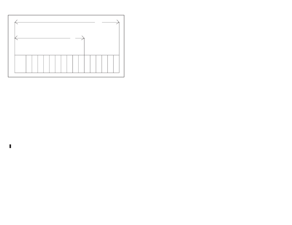
3Ć2
P/S
0
1
2
3
4
5
6
7
8
9 10 11 12 13 14 15
10
10 Slot Rack
16
16 Slot Rack
Figure 3.1 Ć Rack Slot Numbers
Step 5.
Attach the pulsetach but leave the mechanical coupling
between the pulsetach and the motor or flowmeter
unconnected.
Fasten the field wires from the pulsetach to the cable
assembly's terminal strip. Typical field connections are
shown in figures 3.2 to 3.5.
Note that 5V openĆcollector inputs require 464 ohm, 1/2
watt pullĆup resistors while 12V openĆcollector inputs
require 1000 ohm, 1/2 watt pullĆup resistors. Also note
that the output openĆcollector transistors in the pulsetach
should have more than 12 mA of current driving
capability.
Use twistedĆpair wire, connected as shown, for the
cabling between the pulsetach and the terminal strip. If
you use wire with less than 2 twists per inch, it should be
shielded. Note that the shield should only be connected
at one end. Ground the cable shield on the module side.
The recommended twistedĆpair wire is Beldent 8761
cable or equivalent.
Cable length should not exceed 600 feet. Maximum
operating cable length for your installation is dependent
upon the type of cable you use and the way the
pulsetach is wired to the module.
Step 6.
Mount the pulsetach's external power supply. The
external power supply should be able to provide either 5 V
at 25 mA plus the pulsetach's power requirements or
12 V at 25 mA plus the pulsetach's power requirements.
Check the specifications of the pulsetach you will be
using.
Fasten the wires from the power supply to the pulsetach.
For best results, the power supply voltage should be
adjusted to provide the specified voltage at the pulsetach.