Wiring motor power, thermals, and brakes – Rockwell Automation 8520 9/Series Hardware TAB 5 User Manual
Page 91
12
10
8
6
4
2
11
9
7
5
3
1
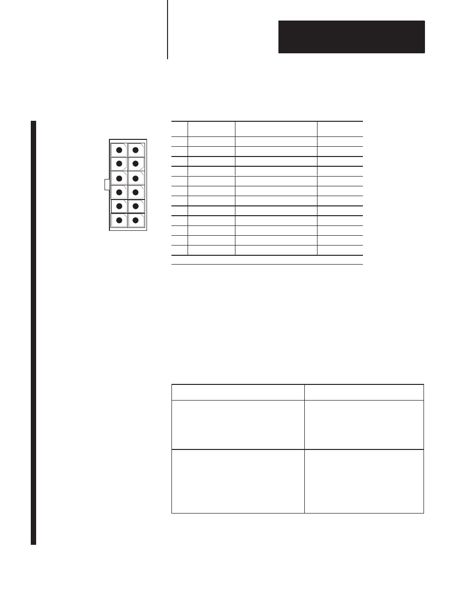
View of connector
on the end of the
feedback cable
Section 5B
9/440HR CNC/Drive System
5B-17
Figure 5B.12
Connecting the 1326 HIPERFACE Motor–mounted Devices on the 9/440HR
CNC/Drive
Pin
Signal
Description
Wire Color
1
Overall Shield
PE
Green/Yellow
2
Supply GND
Encoder Supply Ground
White
3
Supply Power
Encoder Supply Power
1
Black
4
Wire Pair Shield
PE
Clear
5
RS485_LO
Serial Data Low
Green
6
RS485_HI
Serial Data High
Black
7
Wire Pair Shield
PE
Clear
8
CHB_LO
Feedback Device Channel B Low
Black
9
CHB_HI
Feedback Device Channel B High
Blue
10
Wire Pair Shield
PE
Clear
11
CHA_LO
Feedback Device Channel A Low
Black
12
CHA_HI
Feedback Device Channel A High
Red
1
HIPERFACE devices (J1–J4) use 9.7V. A quad B devices (J9–J12) use 5V dc.
Wiring Motor Power, Thermals, and Brakes
The procedures in this section assume that your system and axis modules
are already mounted. We recommend that you start at either the first or
last axis module, wire it completely, and then wire the module next to it
completely, and so on until they are all wired.
To wire your 1394 axis:
1.
If you have this type of system module:
then:
Series A or B
1. Bond one end of the axis module ground
wire to the subpanel.
2. Connect the other end of the ground wire
to terminal block PE1.
3. Go to main step 7.
Series C
1. Connect one end of the axis module
ground wire to the system module ground
bar.
2. Connect the other end of the ground wire
to terminal block PE1.
3. Go to main step 2. Refer to Figure 5B.13
for main steps 2 – 6.
Important: For more information about bonding, refer to your 1394
documentation.