Wiring motor power, thermals, and brakes – Rockwell Automation 8520 9/Series Hardware TAB 5 User Manual
Page 20
1
2
3
4
5
6
7
8
9
10
Section 5A
9/440 Resolver–based CNC/Drive System
5A-18
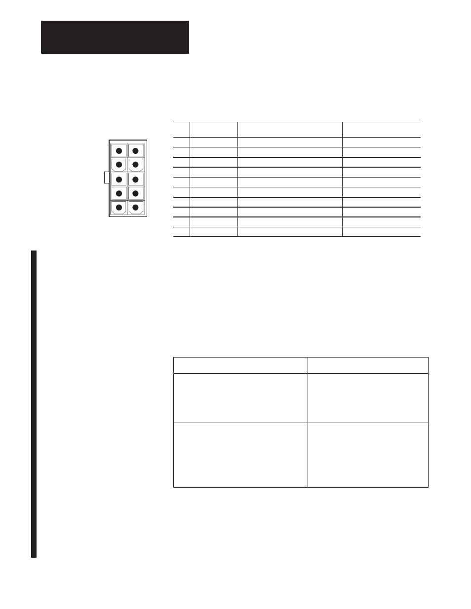
Figure 5A.10
Pin Configuration for the Resolver Connectors on the 9/440 Resolver–based
CNC/Drive
Pin
Signal
Description
Signal Destination
1
R1
Resolver Excitation +
Resolver
2
Shield
Shield Excitation (R1/R2)
3
S1
Feedback Sin +
Feedback Board
4
S2
Feedback Cos +
Feedback Board
5
Shield
Shield Cos. (C1/C2)
6
R2
Resolver Excitation –
Resolver
7
Shield
Shield Sin (S1/S2)
8
C1
Feedback Sin –
Feedback Board
9
C2
Feedback Cos –
Feedback Board
10
Shield
Overall Shield
Wiring Motor Power, Thermals, and Brakes
The procedures in this section assume that your system and axis modules
are already mounted. We recommend that you start at either the first or
last axis module, wire it completely, and then wire the module next to it
completely, and so on until they are all wired.
To wire your 1394 axis:
1.
If you have this type of system module:
then:
Series A or B
1. Bond one end of the axis module ground
wire to the subpanel.
2. Connect the other end of the ground wire
to terminal block PE1.
3. Go to main step 7.
Series C
1. Connect one end of the axis module
ground wire to the system module ground
bar.
2. Connect the other end of the ground wire
to terminal block PE1.
3. Go to main step 2. Refer to Figure 5A.11
for main steps 2 – 6.
Important: For more information about bonding, refer to your 1394
documentation.
Important: To improve the bond between the motor cable shield and the
axis module PE ground, a cable shield clamp is included with the Series C
axis modules.