Rockwell Automation 8520 9/Series Hardware TAB 5 User Manual
Page 136
Section 5B
9/440HR CNC/Drive System
5B-62
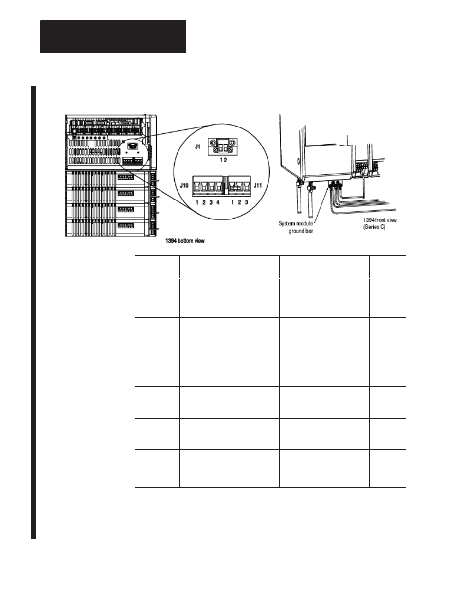
Figure 5B.48
Connectors for 5 and 10 kW Series C System Module
Wire
Description
Maximum
Wire Size
Connects to
Terminal(s)
Required
(Y/N)
24V Logic
A user–supplied 24V ac rms or 24V
dc power source. Refer to your 1394
documentation for 24V input power
specifications.
3.3 mm
2
(12 AWG)
J1–1 and J1–2
Y
360/480V ac
Input Power
360/480V ac, three–phase power
input. Make sure to bundle your
three–phase power together with
neutral as much as possible. Refer
to your 1394 documentation for
system specifications for rated ac
input voltage, tolerance, and source
impedance.
5.3 mm
2
(10 AWG)
J10–1 (U),
J10–2 (V), and
J10–3 (W)
Y
Input Power
Neutral
Three–phase input neutral (present
only on grounded power
configurations)
5.3 mm
2
(10 AWG)
J10–4
N
PE Ground
The 1394’s ground connection to the
bonded system ground bar on the
subpanel.
8.4 mm
2
(8 AWG)
System
Module
Ground Bar
Y
External Shunt
Resistor
Optional 1400W external shunt
resistor used to dissipate excess
regenerative energy from the system
module
5.3 mm
2
(10 AWG)
J11–3 and
J11–1
N
Important: Refer to your 1394 documentation for information about
three–phase input fusing and circuit breaker information as related to the
power input. Refer to the same documentation for information about
wiring the optional shunt resistor to the 5 and 10 kW system modules.