Rockwell Automation 8520 9/Series Hardware TAB 5 User Manual
Page 106
Section 5B
9/440HR CNC/Drive System
5B-32
!
ATTENTION: From a safety standpoint, it is preferred
that the touch probe relay be closed at rest and open when
the touch probe stylus deflects. Then, if a wire breaks or
shorts to ground, it will appear to the system as a probe
fired and the probing cycle in process will stop
commanding motion towards the part. The user should
make every effort towards the fail-safe operation of the
touch probe. Not all vendor’s touch probe control units
conform to this safety consideration.
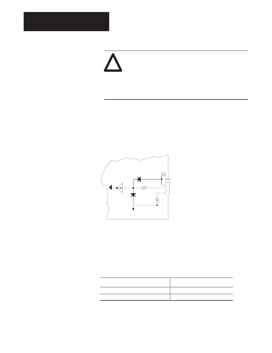
Figure 5B.21 shows the internal servo module circuitry that interfaces to
the touch probe connector. It is shown here to assist you in determining
whether your touch probe hardware is compatible.
Figure 5B.21
Internal Circuitry Supporting the Touch Probe
11309-I
4
3
2
1
9/440HR Wiring Board
470 ohm
5V common
1000 ohm
+5 V dc Encoder Power
+5V Power
TP IN
GND
Shield
to encoder interface
The following table indicates probing threshold voltages. Maximum Input
Threshold (critical if the control has been configured to fire on the falling
edge of the probe signal) indicates the voltage that the probe signal must
fall below to be considered as “fired”. Minimum Input Threshold (critical
if the control has been configured to fire on the rising edge of the probe
signal) indicates the voltage that the probe signal must rise above to be
considered as fired
Probe Thresholds
Voltage at Threshold
Minimum Input Threshold (probe circuit)
3.06 (min)
Maximum Input Threshold (probe circuit)
2.18V dc (max)