Rockwell Automation 8520 9/Series Hardware TAB 5 User Manual
Page 34
Section 5A
9/440 Resolver–based CNC/Drive System
5A-32
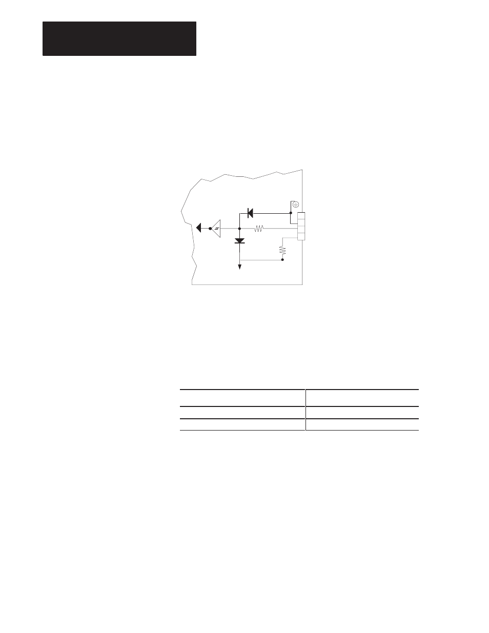
Figure 5A.19 shows the internal servo module circuitry that interfaces to
the touch probe connector. It is shown here to assist you in determining
whether your touch probe hardware is compatible.
Figure 5A.19
Internal Circuitry Supporting the Touch Probe
11309-I
4
3
2
1
9/440 Resolver–based Control
Wiring Board
470 ohm
5V common
1000 ohm
+5 V dc Encoder Power
+5V Power
TP IN
GND
Shield
to encoder interface
The following table indicates probing threshold voltages. Maximum Input
Threshold (critical if the control has been configured to fire on the falling
edge of the probe signal) indicates the voltage that the probe signal must
fall below to be considered as “fired”. Minimum Input Threshold (critical
if the control has been configured to fire on the rising edge of the probe
signal) indicates the voltage that the probe signal must rise above to be
considered as fired
Probe Thresholds
Voltage at Threshold
Minimum Input Threshold (probe circuit)
3.06 (min)
Maximum Input Threshold (probe circuit)
2.18V dc (max)
To avoid misfires use the threshold values from the above table to
determine the necessary signal voltage for steady state operation (probe not
fired). For probes configured to fire on the falling edge the steady state
voltage must remain above 3.06 volts. For probes configured to fire on the
rising edge the steady state voltage must remain below 2.18 volts.