Rockwell Automation 8520 9/Series Hardware TAB 5 User Manual
Page 27
1
2
3
4
5
6
7
8
9
10
11
12
Section 5A
9/440 Resolver–based CNC/Drive System
5A-25
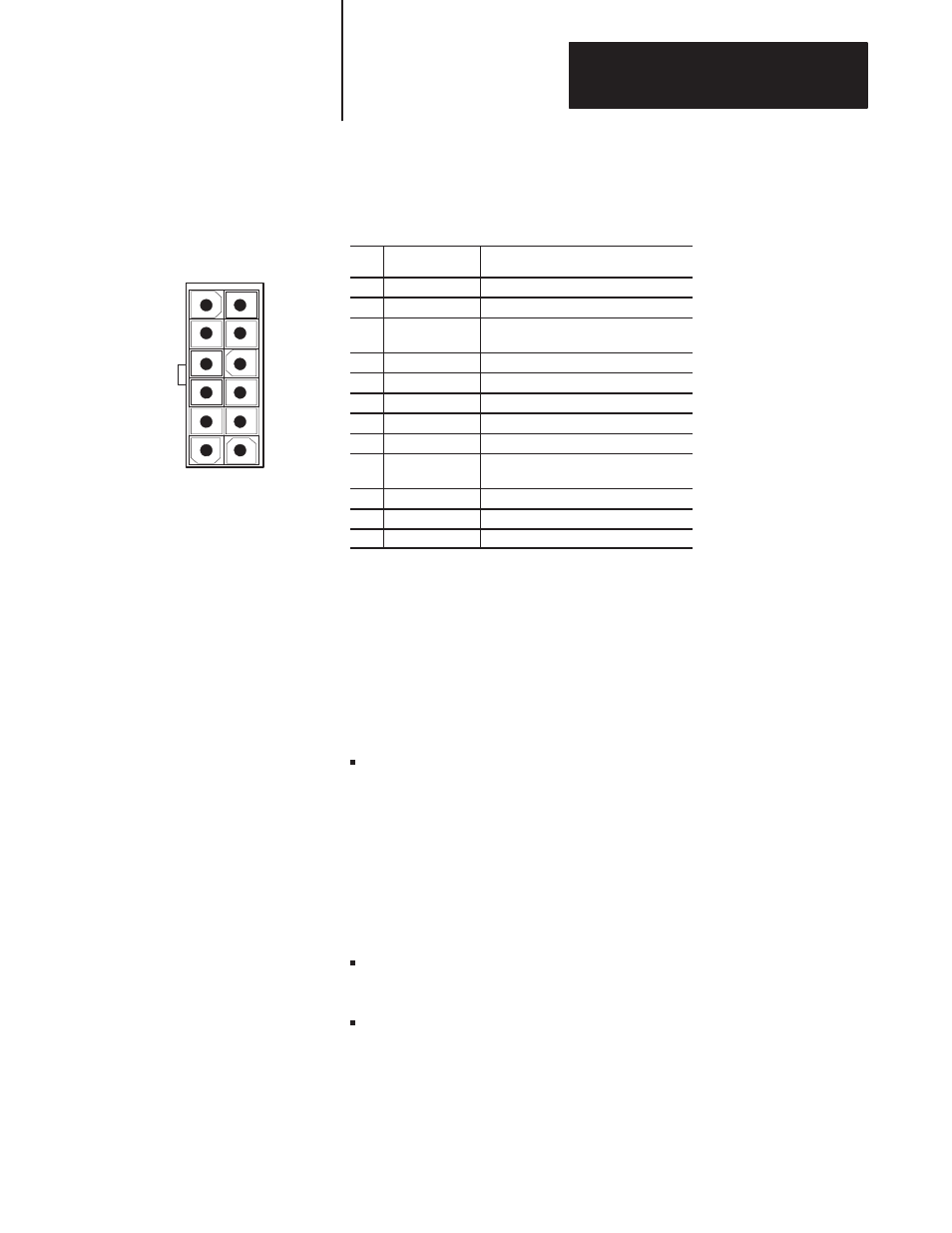
Figure 5A.15
Pin Configuration for the Encoder Connectors on the 9/440 Resolver–based
CNC/Drive
Pin
Signal
Description
1
CHA_HI
Feedback device Channel A
2
Shield
Chassis Ground
3
CHB_HI
Feedback device Channel B
(connect to B_LO on 845H)
4
N/C
no connection
5
CHZ_HI
Feedback device Channel Z
6
GND
Encoder Return
7
CHA_LO
Feedback device Channel A
8
Shield
Chassis Ground
9
CHB_LO
Feedback device Channel B
(connect to B_HI on 845H)
10
N/C
no connection
11
CHZ_LO
Feedback device Channel Z
12
+5V_ENC
+5V Encoder Power Supply
Compatible Optional Feedback Devices and Spindle Feedback
This section discusses optional feedback devices that are compatible with
the 9/440. The 9/440 resolver–based control supplies these devices with
+5V power. Feedback devices must return a 5V compatible output signal
to the control.
This feedback device can be used to provide:
auxiliary position feedback – Digital systems require the motor mounted
feedback device, provided on our standard digital servo motors, be used
for velocity loop feedback. This motor mounted feedback device can
also be used to close the position loop or an additional auxiliary
feedback device, as discussed in this section, can be used for the
position loop. You can not replace or bypass the motor mounted
feedback device. The motor mounted feedback device must be used for
velocity feedback and to attain proper motor commutation on digital
servo systems.
spindle
feedback
– Provide position feedback for your spindle using
these encoder ports.
analog servo feedback – If you are using one of the two analog ports to
control an axis these encoder ports can be used for its position feedback.