4 - programming the redipanel modules, Chapter objectives, Module bit addresses – Rockwell Automation 2705 RediPanel Push Button Module User Manual
Page 40: Programming the redipanel modules, Chapter objectives module bit addresses
A–B
4
Chapter
4–1
Programming the RediPANEL Modules
This chapter provides information on programming a RediPANEL module
from a PLC or SLC controller. For additional programming information
refer to the user manual for your controller or scanner module.
Section
Page
Module Bit Addresses
4–1
Using a PLC-2 with a 1772-SD2 Scanner
4–9
Using a PLC-2 with a Sub I/O Scanner
4–11
Using a PLC-5
4–14
Using a PLC-5 with a Sub I/O Scanner
4–15
Operating Cycles
4–19
Response Time
4–20
Handshake Mode
4–21
Flashing Lamp Example
4–23
SLC-5/02 Programming Example
4–24
Each push button on the RediPANEL module is assigned a bit address. You
need to know these addresses when writing your PLC program. These bit
addresses are the same for all PLC processors.
This section shows the bit address locations for 8, 16 and 32 button modules.
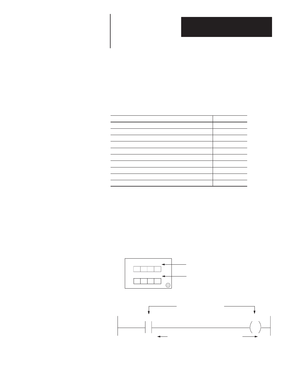
Bit Addresses for 8 Button Modules (Type 800A only)
Octal and Decimal
00 01 02 03
04 05 06 07
1
2
3
4
5
6
7
8
Bit addresses 00 through 07 of the starting
I/O Group Numbers are assigned to lamps
and push buttons 1 through 8.
Starting I/O Group Number
The PLC example below shows where these bit addresses appear in your instruction address.
03
03
X X X
X X X
Bit Address
Push Button #4
Bit Address
for Lamp #4
Chapter Objectives
Module Bit Addresses