And i, Or v, And l – Rockwell Automation 1797-XXX FLEX Ex System Certification Reference Manual User Manual
Page 212: Of the associated apparatus are greater than c, Respectively for the intrinsically safe apparatus, Terminals v, V) i, Ma) groups c, Μ f) l
Publication 1797-6.5.6 - June 2005
46-4 1797-IE8NF FLEX Ex 8 Input Analog Module with Noise Filter
Table 2: Flexbus Entity Values Which are Allowed for the Next
FLEX Ex I/O Module
Table 3: Flexbus Entity Values for this Module
Note: Any combination of up to eight FLEX Ex I/O modules may be
attached on a flexbus.
The entity concept allows interconnection of intrinsically safe apparatus
with associated apparatus not specifically examined in combination as a system
when the approved values of V
oc
and I
sc
or V
t
and I
t
of the associated apparatus
are less than or equal to V
max
and I
max
of the intrinsically safe apparatus and the
approved values of C
a
and L
a
of the associated apparatus are greater than C
i
+
C
cable
and L
i
+ L
cable
respectively for the intrinsically safe apparatus.
Simple apparatus is defined as a device which neither generates nor stores
more than 1.2V, 0.1A, 20µJ, or 25mW.
Terminals
V
t
(V)
I
t
(mA)
Groups
C
a
(
µF)
L
a
(
µH)
Male Bus
Connector
5.8
400
A-G
3.0
3.0
Terminals
V
max
(V)
I
max
(mA)
Groups
C
i
(
µF)
L
i
(
µH)
Female Bus
Connector
5.8
400
A-G
1.35
0
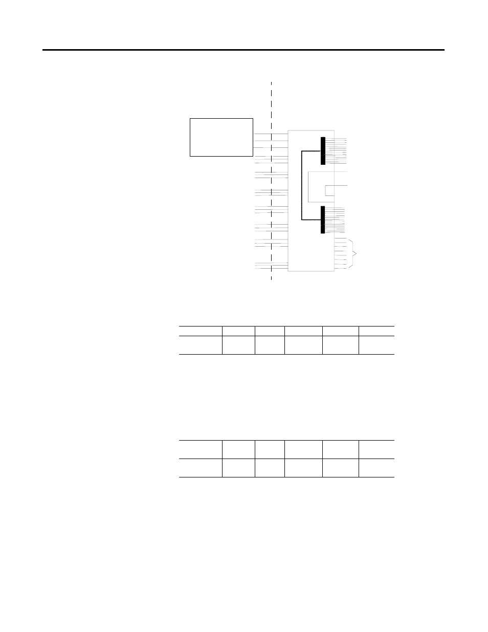
Hazardous (Classified) Location
Class I, Zone 0 Group IIC
Class I, Div. 1 Groups A, B, C, D
Class II, Div. 1 Groups E, F, G
Class III, Div. 1
Hazardous (Classified) Location
Class I, Zones 1 Group IIC
Class I, Div. 1 Groups A, B, C, D
For connection to other
modules, refer to the General
FM Certification Information
on page 38-1.
1797-IE8NF
16
Shield Connection Only
50
51
35
34
V
max
=5.8V
I
max
=400mA
C
i
=1350nF
L
i
=0
V
max
=9.5V
I
max
=1A
C
i
=0
L
i
=0
Male Bus
Connector
33
40
41
42
43
44
45
0 (+)
Female Bus
Connector
Any Simple Apparatus or FM
approved device with Entity
Concept parameters (V
max
, I
max
,
C
i
, L
i
) appropriate for connection
to associated apparatus with
Entity Concept parameters listed
in Table 1: Entity Values for Field
1 (sig)
ch0
ch1
ch2
ch3
ch4
ch5
ch6
ch7
2 (-)
4 (+)
5 (sig)
6 (-)
8 (+)
9 (sig)
10 (-)
12 (+)
13 (sig)
14 (-)
17 (+)
18 (sig)
19 (-)
21 (+)
22 (sig)
23 (-)
25 (+)
26 (sig)
27 (-)
29 (+)
30 (sig)
31 (-)
42483
For connection to other
modules, refer to the General
FM Certification Information
on page 38-1.
From FM approved devices,
1797-PS1N, -PS2N, or
-PS2N2.