Rockwell Automation 1797-XXX FLEX Ex System Certification Reference Manual User Manual
Page 194
Publication 1797-6.5.6 - June 2005
42-4 1797-IBN16 FLEX Ex 16 NAMUR Input Module
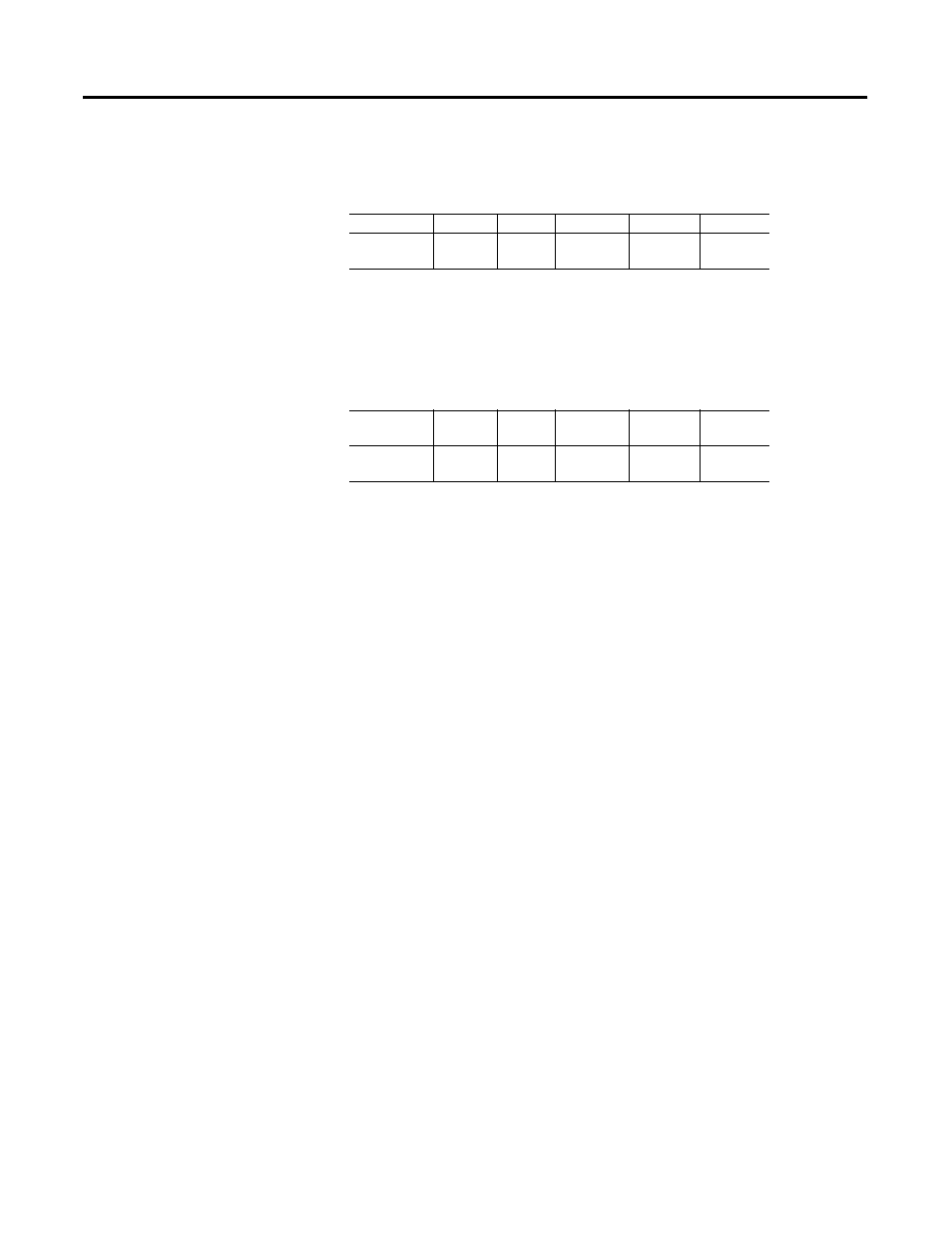
Table 2: Flexbus Entity Values Which are Allowed for the Next
FLEX Ex I/O Module
Table 3: Flexbus Entity Values for this Module
Note: Any combination of up to eight FLEX Ex I/O modules may be
attached on a flexbus.
The entity concept allows interconnection of intrinsically safe apparatus
with associated apparatus not specifically examined in combination as a system
when the approved values of V
oc
and I
sc
or V
t
and I
t
of the associated apparatus
are less than or equal to V
max
and I
max
of the intrinsically safe apparatus and the
approved values of C
a
and L
a
of the associated apparatus are greater than C
i
+
C
cable
and L
i
+ L
cable
respectively for the intrinsically safe apparatus.
Simple apparatus is defined as a device which neither generates nor stores
more than 1.2V, 0.1A, 20µJ, or 25mW.
Wiring methods must be in accordance with the National Electric Code,
ANSI/NFPA 70, Article 504 and 505. For additional information refer to
ANSI/ISA RP12.6.
This module, 1797-IBN16, must be used with terminal base 1797-TB3 or
1797-TB3S.
Terminals 36-39, and 46-49 shall not be connected.
Any combination of up to eight channels may be connected in parallel and
connected to simple apparatus in a hazardous location. If two channels are
connected in parallel, the total cable inductance must be limited to 20mH for
Groups A and B, 80mH for Groups C and E, and 160mH for Groups D, F,
and G. If eight channels are connected in parallel, the total cable inductance
must be limited to 2mH for Groups A and B, 8mH for Groups C and E and
16mH for Groups D, F, and G.
WARNING: Substitution of components may impair intrinsic safety.
Terminals
V
t
(V)
I
t
(mA)
Groups
C
a
(
µF)
L
a
(
µH)
Male Bus
Connector
5.8
400
A-G
3.0
3.0
Terminals
V
max
(V)
I
max
(mA)
Groups
C
i
(
µF)
L
i
(
µH)
Female Bus
Connector
5.8
400
A-G
0
0