Rockwell Automation Logix5000 Controllers Sequential Function Charts Programming Manual User Manual
Page 19
Design a sequential function chart
Chapter 1
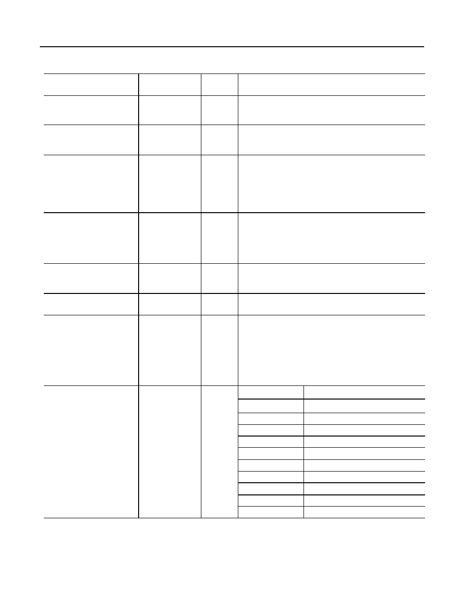
If you want to
Then select or set this
member
Data type
Details
Do something one time when the step
becomes active
FS
1
BOOL
The FS bit is on during the first scan of the step.
Typically, we recommend that you use an action with a P1 Pulse (Rising Edge) qualifier
to accomplish this.
Do something while the step is active,
except on the first and last scan
SA
BOOL
The SA bit is on when the step is active except during the first and last scan of the step.
Do something one time on the last scan of
the step
LS
1
BOOL
The LS bit is on during the last scan of the step.
Use this bit only if on the Controller Properties dialog box, SFC Execution tab, you
set the Last Scan of Active Step to Don’t Scan or Programmatic reset.
Typically, we recommend that you use an action with a P0 Pulse (Falling Edge) qualifier
to accomplish this.
Determine the target of an SFC Reset (SFR)
instruction
Reset
BOOL
An SFC Reset (SFR) instruction resets the SFC to a step or stop that the instruction
specifies.
The Reset bit indicates the step or stop where the SFC goes to begin executing again.
Once the SFC executes, the Reset bit clears.
Determine the maximum time that a step
has been active during any of its executions
TMax
DINT
Use this for diagnostic purposes. The controller clears this value only when you set
the Restart Position to Restart at initial step and the controller changes modes or
experiences a power cycle.
Determine if the Timer (T) value rolls over
to a negative value
OV
BOOL
Use this for diagnostic purposes.
Determine how many times a step has
become active
Count
DINT
This is not a count of scans of the step.
• The count increments each time the step becomes active.
• It increments again only after the step goes inactive and then active again.
• The count resets only if you configure the SFC to restart at the initial step. With that
configuration, it resets when the controller changes from program mode to run
mode.
Use one tag for the various status bits of
this step
Status
DINT
For this member
Use this bit
Reset
22
AlarmHigh
23
AlarmLow
24
AlarmEn
25
OV
26
DN
27
LS
28
SA
29
FS
30
X
31
(1) The FS and LS bits are only active during a step’s execution. Once a step finishes executing the code within its actions, the FS or the
LS or both bits are reset. If you reference either of these bits in code outside of the SFC routine in a different part of the project, the
bits are always cleared (0).
Rockwell Automation Publication 1756-PM006F-EN-P - October 2014
19