Rockwell Automation 1794 FLEX I/O System with ControlLogix for SIL2 User Manual
Page 36
Publication 1794-RM001G-EN-P - December 2011
3-14 FLEX I/O Modules
•
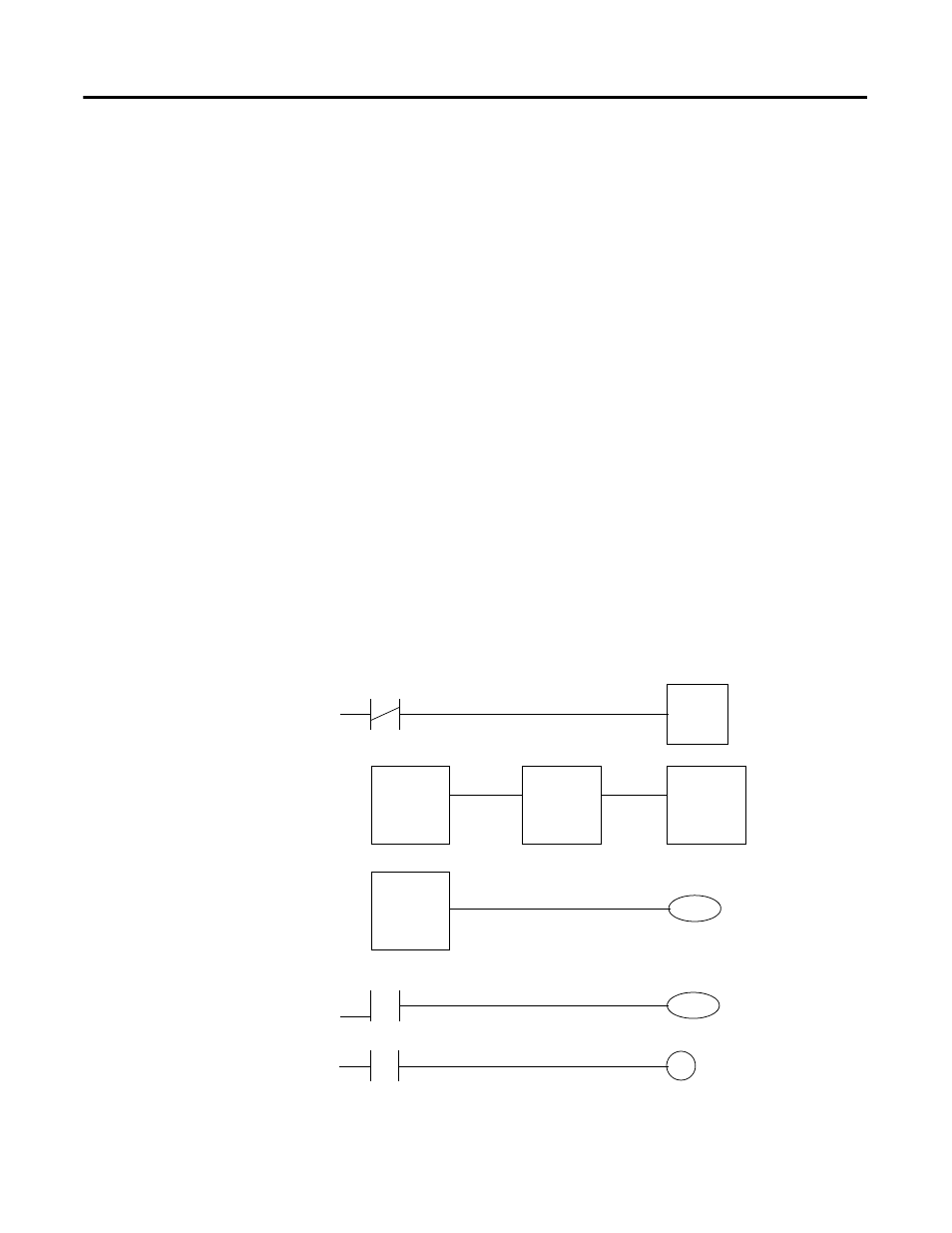
Wire Output Back to Input and Examination of Output Data
Feedback signal: Users must wire an analog output to an actuator and
then back to an analog input to monitor the output’s performance. (The
use of feedback transmitters to verify an output’s performance is
acceptable.) The application logic must examine the Data Feedback
value associated with each output point to make sure that the requested
output command from the controller was received by the module. The
value must be compared to the analog input that is monitoring the
output to make sure the value is in an acceptable range for the
application.
In the ladder diagram in Figure 3.12, a user-defined percentage of
acceptable deviation (that is, tolerance) is applied to the configured
range of the analog input and output (that is, range) and the result is
stored (that is, delta). This delta value is then added to and subtracted
from the monitoring analog input channel; the results define an
acceptable High and Low limit of deviation. The analog Output
Feedback is then compared to these limits to determine if the output are
working properly.
The output’s OK bit preconditions a Timer run that is preset to
accommodate an acceptable fault response time and any communication
filtering, or output, lags in the system. If the monitoring input value and
the Output Feedback miscompare for longer than the preset value, a
fault is registered with a corresponding alarm.
Figure 3.12 Monitoring an Analog Output with an Analog Input
The control, diagnostics and alarming functions must be performed in
sequence.
Timer done
Timer
Outputs Faulted
Alarm to Operator
Outputs OK
ADD
Delta
Monitoring input
High Limit
MULT
Range
Tolerance %
Delta
Outputs Faulted
LIM
Low Limit
Output Echo
High Limit
Outputs OK
SUB
Delta
Monitoring input
Low Limit