Wiring flex i/o digital output modules, Standard digital output modules – Rockwell Automation 1794 FLEX I/O System with ControlLogix for SIL2 User Manual
Page 27
Publication 1794-RM001G-EN-P - December 2011
FLEX I/O Modules 3-5
•
Monitor the ControlNet status bits for the associated module and
ensure that appropriate action is invoked via the application logic by
these status bits.
Wiring FLEX I/O Digital
Output Modules
Standard Digital Output Modules
When using standard output modules, users must wire an output to an
actuator and then back to an input to monitor the output’s performance.
In addition to following the General Considerations when using Any FLEX
I/O Digital Output Module on page 3-4, the user must wire each standard
output to a corresponding input to validate that the output is following its
commanded state.
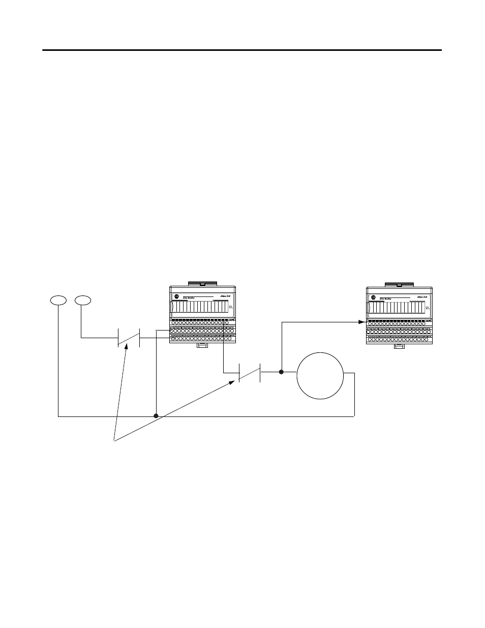
Figure 3.5 ControlLogix/FLEX I/O Standard Output Module Wiring
Application logic must be written to generate a fault in the event of a
miscompare between the requested state of an output (echo) and the actual
output state monitored by an input channel (see Figure 3.4).
The control, diagnostics and alarming functions must be performed in
sequence.
1 2
3 4 5
6 7
8 9 10 11 12 13 14 15
0
24VDC SOURCE OUTPUT
1794-OB16
1 2
3 4 5
6 7
8 9 10 11 12 13 14 15
0
24VDC SINK INPUT
1794-IB16
Standard Digital
Output Module
43363
Standard Digital
Input Module
+24V
COM
Output
Actuator
Install a relay in position A or B. This relay is controlled by another
output in the ControlLogix/FLEX I/O system. If a short circuit or fault
occurs on output modules, the relay can disconnect power to the
modules. An isolated relay output module (1794-OW8) can be used for
this purpose when it is connected to a different 1794-ACN15 or
-ACNR15 ControlNet Adapter module.
Wire output point
to input point to
verify the correct
state of the output
COM
24V dc
A
B
Note: Other configurations are possible as long they are
SIL2 approved.