Wire the module, I/o connectors, Ethernet/ip connectors – Rockwell Automation 1732E-IB16M12SOEDR EtherNet/IP ArmorBlock supporting Sequence of Events User Manual
Page 22
Publication 1732E-UM002A-EN-P - March 2010
14 Install Your Module
Wire the Module
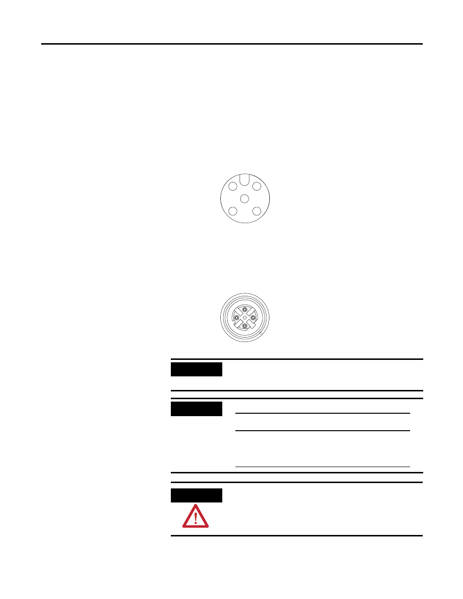
The ArmorBlock EtherNet/IP family has 5-pin micro-style I/O connectors.
We provide caps to cover the unused connectors on your module. Connect the
quick-disconnect cord sets you selected for your module to the appropriate
ports.
I/O Connectors
Refer to the pinout diagrams for the I/O connectors.
Ethernet/IP Connectors
Refer to the pinout diagrams for the network connectors
. .
IMPORTANT
Use the 1585D–M4DC–H: Polyamide small body unshielded or the
1585D–M4DC–SH: Zinc die-cast large body shielded mating
connectors for the D-Code M12 female network connector.
IMPORTANT
Use two twisted pair CAT5E UTP or STP cable.
ATTENTION
Make sure all connectors and caps are securely tightened to
properly seal the connections against leaks and maintain IP
enclosure type requirements.
1
2
4
5
3
(View into connector)
Pin 1 Sensor Source Voltage
Pin 2 Input B
Pin 3 Return
Pin 4 Input A
Pin 5 PE
Micro-style 5-Pin Input Female Connector
44807
4
2
3
1
5
D-Code M12 Network Female Connector
44808
(View into connector)
Pin 1 M12_Tx+
Pin 2 M12_Rx+
Pin 3 M12_Tx-
Pin 4 M12_Rx-
Pin 5 Connector shell shield FE
D-Code
M12 Pin
Wire Color
Signal
8-way Modular
RJ45 Pin
1
White-Orange
TX+
1
2
White-Green
RX+
3
3
Orange
TX-
2
4
Green
RX-
6