Using i/o image tables for commands and status – Rockwell Automation 1746-QS,D17466.19 SYNCHRONIZED AXES MODULE User Manual
Page 47
Using Processor Files
C–5
Publication 1746-6.19 March 1998
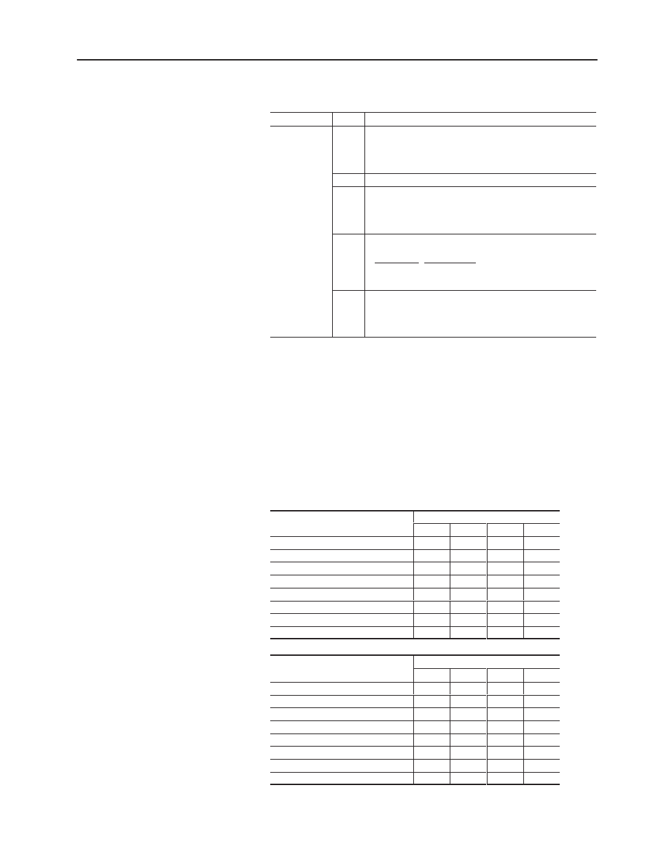
Bit Map of Configuration Word (e:0, e:16, e:32. e:48)
Word
Bit
Description
Configuration
(bit ap)
15-12
Number of LDT recirculations = bit combination.
bit 15 = 8 recirculations
bit 14 = 4 recirculations
bit 13 = 2 recirculations
bit 13 = 1 recirculation
(bit map)
11-04
Reserved
03
Simulate mode, used for debugging.
= 1 Drive output is set to null, LDT inputs are ignored.
Internally, the target position is used as the actual position.
(LDT error bits and LEDs are cleared.)
= 0 Simulate mode ignored.
02-01
Divide LDT counts = bit combination; used to reduce LDT count
resolution for long strokes or high speeds
Bit 02 Bit 01 Divide counts by
0
1
2
1
0
4
1
1
8
0
Integrator limit, to help prevent drive output saturation.
If integrator = limit, integrator windup bit in status word is set, and
integrator value is held to the limit.
=1 limit is 80% of full drive
=0 limit is 20% of full drive
Motion-control command words for all four axes are sent to the
module through the output image table, and axis status words of all
four axes are returned from the module through the input image table.
The ladder program may write 32 command words (for all four axes)
from an integer file to the output image table (by a COPY instruction),
and may read 32 status words (for all four axes) from the input image
table (by a COPY instruction) into another integer file.
Eight output image words per axis (for commands) and eight input
words per axis (for status) are addressed as follows:
Your Ladder Logic Must
To These Output Image Addresses:
Your Ladder Logic Must
Write These Parameters
Axis 1
Axis 2
Axis 3
Axis 4
Mode
O:e.0
O:e.8
O:e.16
O:e.24
Acceleration
O:e.1
O:e.9
O:e.17
O:e.25
Deceleration
O:e.2
O:e.10
O:e.18
O:e.26
Speed
O:e.3
O:e.11
O:e.19
O:e.27
Position/Command Value
O:e.4
O:e.12
O:e.20
O:e.28
Command
O:e.5
O:e.13
O:e.21
O:e.29
Reserved
O:e.6
O:e.14
O:e.22
O:e.30
Reserved
O:e.7
O:e.15
O:e.23
O:e.31
Your Ladder Logic Must
Rea These arameters
At These Input Image Addresses:
Your Ladder Logic Must
Read These Parameters
Axis 1
Axis 2
Axis 3
Axis 4
Commanded Position
I:e.0
I:e.8
I:e.16
I:e.24
Target Position
I:e.1
I:e.9
I:e.17
I:e.25
Actual Position
I:e.2
I:e.10
I:e.18
I:e.26
LDT Counts
I:e.3
I:e.11
I:e.19
I:e.27
Status Bits
I:e.4
I:e.12
I:e.20
I:e.28
Drive Output
I:e.5
I:e.13
I:e.21
I:e.29
Actual Speed
I:e.6
I:e.14
I:e.22
I:e.30
Drive Null
I:e.7
I:e.15
I:e.23
I:e.31
Using I/O Image Tables
for Commands and Status