6 - troubleshooting, Objectives, Using led indicators – Rockwell Automation 1746-QS,D17466.19 SYNCHRONIZED AXES MODULE User Manual
Page 37: Correcting typical problems, Troubleshooting, Chapter
Chapter
6
Publication 1746-6.19 March 1998
Troubleshooting
This chapter:
•
Describes the module’s LED indicators
•
Suggests corrective action for typical operating problems
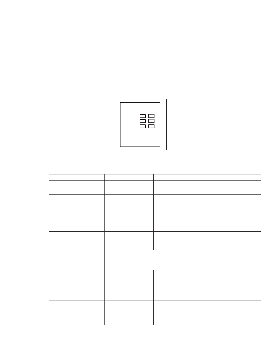
Use this table to interpret the module’s LED-indicated status.
HYDRAULIC
SYNCHR AXES
AXES 1
RUN/FLT
3
2
4
Module “Run” status:
Green:
Module OK
Off:
SLC not communicating
Flash Grn: Updating
FLASH
memory
Module ”Fault” status:
Red:
Fault or Power-up reset
Green:
Module power OK
Axis status (one LED per axis):
Red:
LDT error (loss of input, noise)
Green:
Axis OK
Flash Red: Axis motion error
Off:
Axis not initialized
Use this table to look up corrective action for typical problems.
Problem Condition:
Possible Cause:
Corrective Action – Check the Following:
Ladder program cannot:
– access parameters
– operate the module
You made errors configuring
the module or addressing
your ladder logic.
1) module is not configured properly
2) module’s I/O slot number and ladder address do not match
Red Axis LEDs are on
The transducer is not
responding to the module.
1) Status word to determine which transducer fault has occurred
2) Transducer power supply and wires to the transducer
During a move, the
Actual Position is erratic
Incorrect shielding or a
defective transducer is
causing electrical noise.
Monitor bits 13, 14, and 15 of the axis’
STATUS
word to determine if
the module is detecting a transducer error. To reduce electrical noise:
1) Make sure the transducer wiring is separated from all other wiring.
2) Add a termination resistor (220 ohm for Temposonics I) as close
to the transducer as possible.
3) Connect the shield at the module end, transducer end, or both.
During a move, the
drive halts for no apparent reason
When the module detects a
“transducer not responding”
error it stops automatically.
See “...Actual Position is erratic” above for more information.
If any of the following conditions are enabled, the axis will also halt:
– Following Error
– Position Overflow
– Integrator Windup
– Overdrive
– Parameter Error
Transducer counts field is not
indicating transducer location
See“’Red Axis LEDs are on” above.
Transducer counts field changes
but output drive does not work
See “...drive halts for no apparent reason” above.
The System is unresponsive
and hard to tune
This problem could have
several causes.
1) Is a hose rather than rigid pipe installed between the hydraulic
valve and the cylinder? The fluid expands the hose rather than
moving the cylinder.
2) Does the valve have overlap? Overlap in hydraulic valves causes
a significant dead band and slows the system response. Some
proportional valve amplifiers have dead band eliminator circuits
which make tuning easier.
The axis oscillates
This problem could have
several causes.
1) The
DEAD BAND ELIMINATOR
value may be too high.
2) Reduce
PROPORTIONAL, INTEGRAL,
or
DIFFERENTIAL
gains.
The axis does not finish moves or
moves differently than expected
The SLC processor is issuing
unintended commands.
Use the Hydraulics Configurator command queue to monitor
commands sent by the SLC processor to the module.
Confirm that only the expected commands are being sent.
Objectives
Using LED Indicators
Correcting
Typical Problems