Wiring example – Rockwell Automation 1746-QS,D17466.19 SYNCHRONIZED AXES MODULE User Manual
Page 11
2–3
Publication 1746-6.19 March 1998
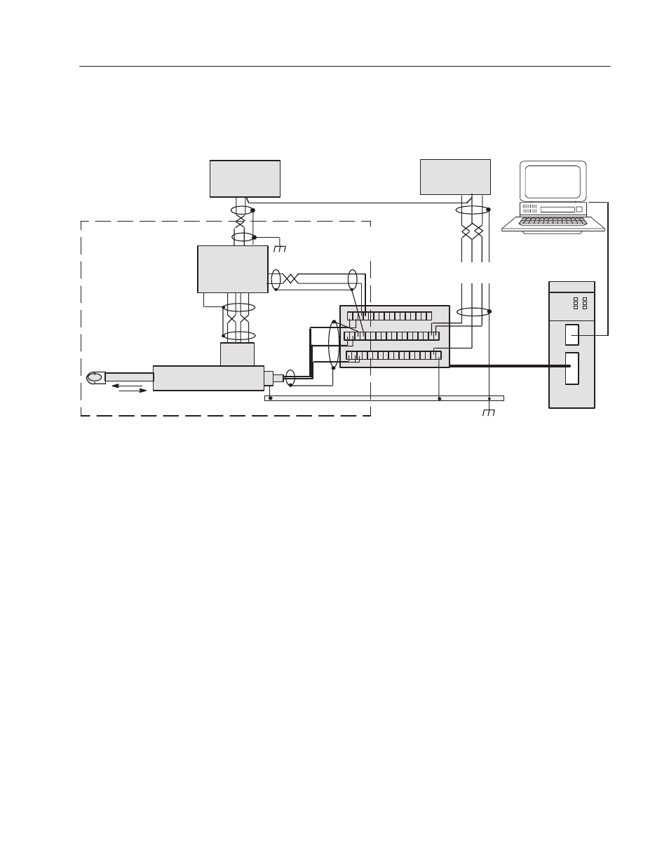
Wiring Example
We present a 1-axis loop with a differential LDT input.
(You must provide power supplies and servo amplifiers.)
Drive Output
Valve
Servo or
Proportional
Amplifier
24V Power
Supply
"15V Power
Supply for LDTs
earth ground
(+) (–)
(–) (C) (+)
Belden
8761
Belden
8761
Belden
8770
Piston-type Hydraulic Cylinder and
Linear Displacement Transducer (LDT)
0V (internal)
+
–
Pwr
Int
Ret
Axis Loop 1 of 4-axis system
IFM Terminal Block
Cat. No. 1492-AIFMQS
Cable 1492-
ACABLExxxQ
Belden
8105
Connect cable shields of LDT
and drive output to SH terminals
on terminal block (to earth GND).
HYDRAULIC
SYNCHR AXES
1746-QS
module
1747-CP3
Cable
Important: The module’s
analog outputs require an
external amplifier to drive
the valve.
Connect signal commons and PS commons
to Com terminals, isolated from earth GND.
Grounding exception:
Connect this shield
to internal common.
Hydraulic
Configurator
Software on PC
Important: Signals in this type of control system are very susceptible to
radiated electrical noise. The module is designed to detect loss-of-sensor
and sensor noise conditions for any of the four axes when position values
are lost or corrupted. The Hydraulic Configurator displays these
conditions in the Status word window. The resulting hard or soft stop
depends on how you configured autostop conditions. (See Hydraulic
Configurator, Config word, and click on autostop “Help“).
To minimize interference from radiated electrical noise with correct
shielding and grounding:
•
Connect LDT cable shields and drive output cable shields (all
shields at one end, only) to IFM terminal block SH terminals, and
connect the IFM terminal block GND terminal (51) to earth ground.
•
Keep LDT signal cables far from motors or proportional amplifiers.
•
Connect all of the following to earth ground:
– power supply cable shields (one end, only)
– LDT flange, frame, and machine
– I/O chassis
– AC ground
•
Use shielded twisted pairs for all connections to inputs and outputs.
•
Run shielded cables only in low-voltage conduit.
•
Place the SLC-500 processor and I/O chassis in a suitable enclosure.
Minimizing Interference
from Radiated Electrical
Noise