Interpreting the indicator lights, What to do next, 2ć10 – Rockwell Automation 1771-TCM,D17716.5.108 TEMPERATURE CONTROL MOD User Manual
Page 22: Interpreting the indicator lights what to do next
Installing the Module
Chapter 2
2-10
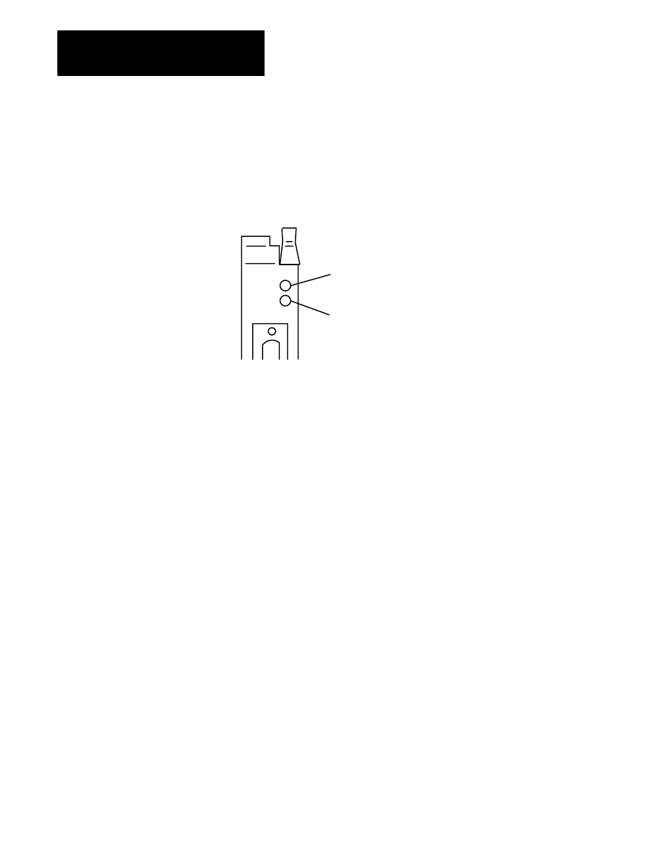
The front panel of the analog module contains two bi-color indicators: a
red/green RUN/FLT (fault) indicator and a red/green CAL/COM indicator
(Figure 2.7).
Figure 2.7
Diagnostic Indicators
RUN/FLT
CAL/COM
10528ĆI
Calibrate/communication indicator. This indicator will flash green
when doing blockĆtransfers. It will flash red during calibration.
Run/Fault indicator. This indicator will flash green until the first
valid blockĆtransfer write has been received. If a fault is found
initially or occurs later, the RUN/FLT indicator turns red.
At power-up, an initial module self-check occurs. When the check is
completed satisfactorily, the RUN/FAULT indicator will start to flash
green. It will continue to flash green until the first valid block-transfer
write has been received. If a fault is found initially or occurs later, the
RUN/FLT indicator turns red.
The bottom indicator is the calibrate/communication indicator. This
indicator will flash green when doing block-transfers. It will flash red
during calibration.
Possible module fault causes and corrective action are discussed in
Chapter 9, “Troubleshooting.”
To learn how to use ladder logic to communicate with the temperature
control module, read chapter 3.
Interpreting the
Indicator Lights
What to do next