Ladder file 2 -19, Ladder file 2 – Rockwell Automation 1746-NI16V SLC 500 Analog Input Modules User Manual User Manual
Page 97
Publication 1746-UM001A-US-P
Application Examples 7-19
Ladder File 2
0000
S:1
15
First Pass
FLL
Fill File
Source
0
Dest
#I:6.0
Length
32
FLL
COP
Copy File
Source
#N7:0
Dest
#O:6.0
Length
16
COP
0001
COP
Copy File
Source
#I:6.16
Dest
#N7:46
Length
16
COP
0002
N7:46
13
N7:46
14
N7:46
15
MOV
Move
Source
I:6.0
0<
Dest
N7:30
0<
MOV
0003
N7:47
13
N7:47
14
N7:47
15
MOV
Move
Source
I:6.1
0<
Dest
N7:31
0<
MOV
0004
N7:48
13
N7:48
14
N7:48
15
MOV
Move
Source
I:6.2
0<
Dest
N7:32
0<
MOV
0005
N7:49
13
N7:49
14
N7:49
15
MOV
Move
Source
I:6.3
0<
Dest
N7:33
0<
MOV
0006
N7:50
13
N7:50
14
N7:50
15
MOV
Move
Source
I:6.4
0<
Dest
N7:34
0<
MOV
0007
N7:51
13
N7:51
14
N7:51
15
MOV
Move
Source
I:6.5
0<
Dest
N7:35
0<
MOV
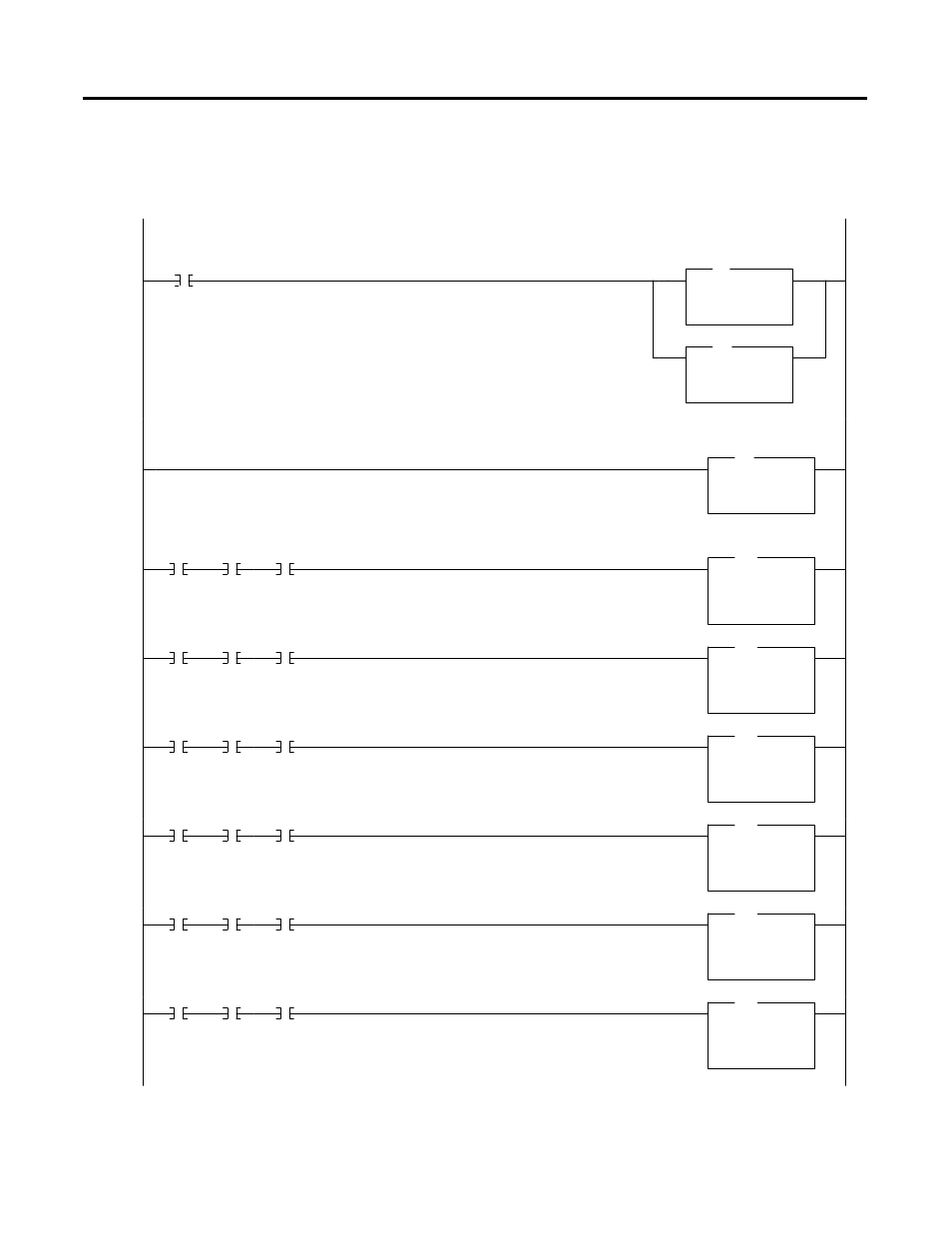
At power-up, clear the input image table for the NI16 to be sure old status and analog data is not used and then copy the configuration
words for each of the analog modules’16 channels. These configuration words are stored from N7:0 through N7:15.
Continually read the 16 status words for the 16 analog channels and store them in data table words N7:61. These words contain “Error
Conditions” for each channel, which are monitored in the following 16 rungs to determine if the data is valid before using it. These
“Error Condition” bits are 13, 14, and 15 of each channel status word, i.e. they must all be set to indicate “No Error” for each channel.
This rung and the following 15 rungs copy the analog data from the 1746-NI16 module’s 16 channels. The data is moved and is therefore
considered valid only when the channels associated status word “Error Condition” bits (13 to 15) are all set indicating “No Error”.