Ladder files -3, Ladder files, File 2 – Rockwell Automation 1746-NI16V SLC 500 Analog Input Modules User Manual User Manual
Page 81
Publication 1746-UM001A-US-P
Application Examples 7-3
Ladder Files
File 2
0000
S:1
15
First Pass
B3:3
1
U
B3:0
2
U
B3:0
1
U
B3:3
0
JSR
Jump To Subroutine
SBR File Number
U:3
JSR
0001
B3:3
1
OSR
B3:0
0
L
B3:0
1
0002
B3:0
1
COP
Copy File
Source
#N7:20
Dest
#O:6.0
Length
8
COP
I:6.0
0
1747-NI16V
I:6.0
1
1747-NI16V
MOV
Move
Source
I:6.0
0<
Dest
N7:50
0<
MOV
L
B3:4
0
I:6.1
0
1747-NI16V
I:6.1
1
1747-NI16V
MOV
Move
Source
I:6.1
0<
Dest
N7:51
0<
MOV
L
B3:4
1
I:6.2
0
1747-NI16V
I:6.2
1
1747-NI16V
MOV
Move
Source
I:6.2
0<
Dest
N7:52
0<
MOV
L
B3:4
2
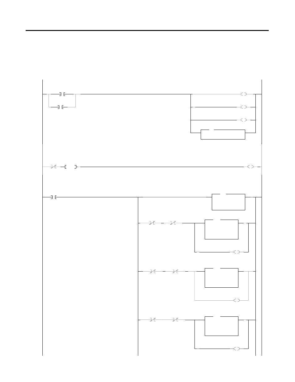
Subroutine file 3 is used to configure all 16 channels of the 1746-NI16. This rung allows subroutine 3 to be scanned until all 16 channels are
configured. The status words for all 16 channels containing the results of the configuration will be placed consecutively beginning with
N7:66.
Once the 16 analog channels are configured, B3/1 is latched to instruct the NI16 module to begin sending analog data to the processor for
the first 8 channels. B3/2 is used in the next rung to instruct the module to send data from the last 8 channels. Since there are only 8 input
image words in Class 1 mode for receiving data from the 16 channel module, this program toggles between the first and last 8 channels and
places the data for all 16 channels consecutively beginning with N7:50.
The COP Instruction copies Control Words for channels 0 to 7, requesting analog data for those channels. The data is received from the
NI16 in input image words I:6.0 through I:6.7, when bits 0 and 1 for each of these input words are both reset. When all 8 inputs are
updated, B3/1 is reset and B3/2 is set to read the data for channels 8 to 15.