Calibration, Calibration sequence, Appendix d – Rockwell Automation 1746-NI16V SLC 500 Analog Input Modules User Manual User Manual
Page 109: Appendix
1
Publication 1746-UM001A-US-P
Appendix
D
Calibration
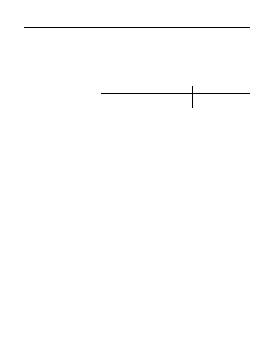
The module should be calibrated to the following values to adhere to
the “Module Error Over Full Temperature Range” specifications in
Appendix A.
Calibration Sequence
The module returns a faulty calibration error if the order of the
calibration sequence is not performed as expected. The calibration
sequence is as follows:
1. Disable the channel to be calibrated by setting bit 15 to 0.
2. Set bit 9 equal to 1 in the configuration word to enter the
calibration mode.
3. Apply a low calibration value from the appropriate range,
according to the table above.
4. Set bit 10 to 1 to accept this input as the new low calibration value.
5. Verify that bit 8 in the appropriate status word has changed to a
1, signifying that the low value calibration was accepted.
6. Change bit 10 in the calibration word back to a 0.
7. Apply a high calibration value to the channel to be calibrated
from the appropriate range according to the table above.
8. Set bit 11 to 1 to accept this input as the new high calibration
value.
9. Verify that bit 9 in the appropriate status word has changed to a
1 signifying the high value calibration was accepted.
10. Change bit 11 in the calibration word back to a 0.
11. Change bit 9 in the configuration word back to a 0 to exit the
calibration mode.
Existing calibration values can be overwritten to re-calibrate a
channel.
Calibration Voltage or Current Range
Module Type
Low Calibration Value
High Calibration Value
1746-NI16V
-0.005 V to +0.005 V
+10.245 V to +10.255 V
1746-NI16I
-0.03 mA to +0.03 mA
+20.97 mA to +21.03 mA