B - configuration worksheet, Appendix b, Configuration worksheet – Rockwell Automation 1746-NI16V SLC 500 Analog Input Modules User Manual User Manual
Page 105: Appendix
1
Publication 1746-UM001A-US-P
Appendix
B
Configuration Worksheet
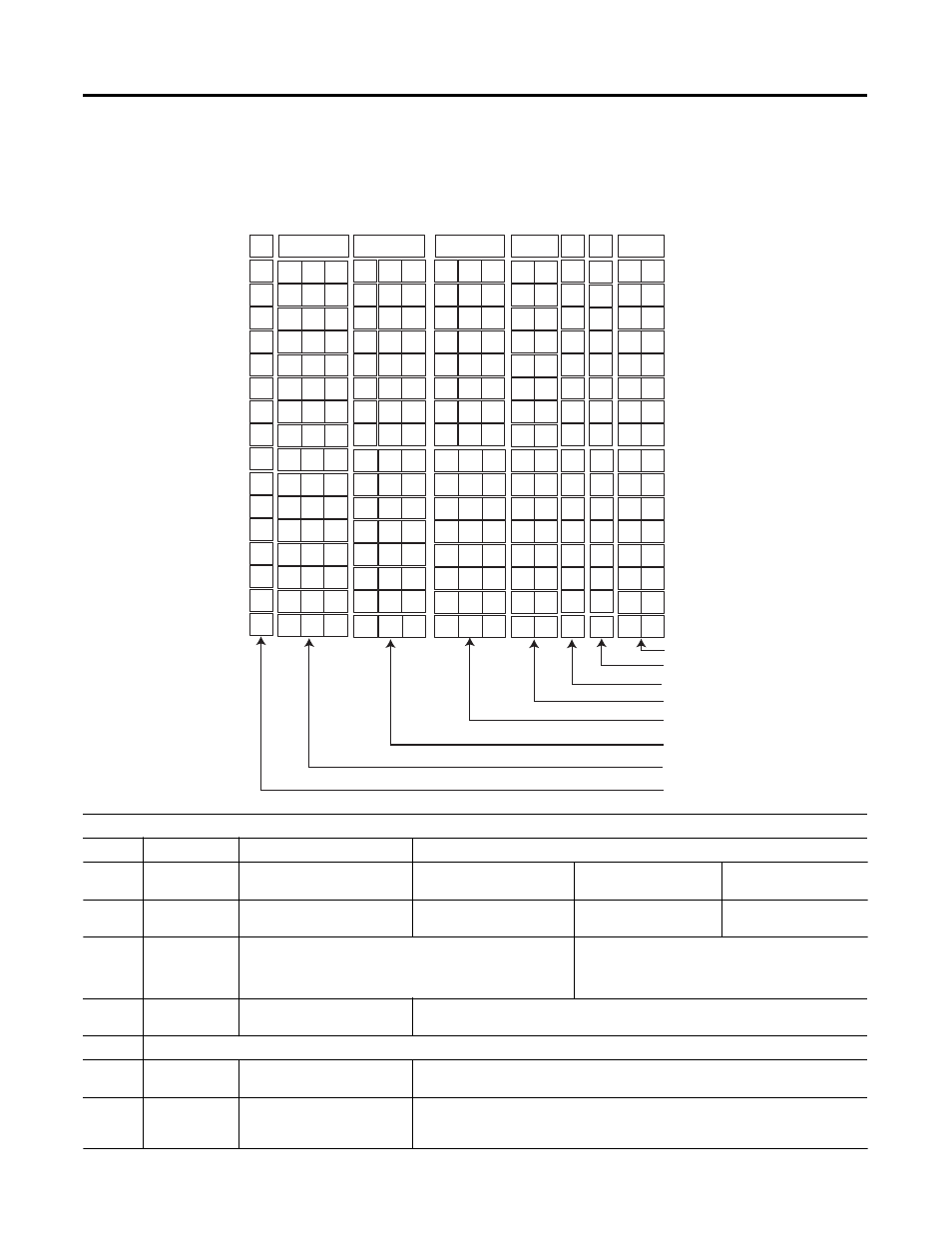
The following worksheet is provided to help you configure each of
the channels on your module. See Chapter 5 for detailed configuration
information.
11
9
10
8
6
7
4
5
0
1
2
3
12
13
14
15
0
0
0
0
0
0
0
0
0
0
0
0
0
0
0
0
Bit Number
Channel 0
Channel 1
Channel 2
Channel 3
Channel 4
Channel 5
Channel 6
Channel 7
•
Class 1 Channel Configuration
•
Class 1 Handshaking
•
Input Type
•
Filter Frequency
•
Channel Enable
•
Not Used
•
Data Format
•
Calibration
Channel 8
Channel 9
Channel 10
Channel 11
Channel 12
Channel 13
Channel 14
Channel 15
Bit Definitions:
Bit 15
Channel Enable
0 = channel disabled
1 = channel enabled
Bits 14-12 Filter Frequency
000 = 6 Hz
001 = 10 Hz
010 = 20 Hz
011 = 40 Hz
100 = 60 Hz
101 = 80 Hz
110 = 100 Hz
111 = 250 Hz
Bits 11-9
Calibration
000 = exit calibration
(normal run mode)
001 = enter calibration
011 = perform zero
calibration
101 = perform full scale
calibration
Bits 8-6
Data Format
Class 1 and Class 3
Class 3 Only
000 = engineering units
001 = scaled-for-PID
010 = proportional counts
011 = 1746-NI4 data format
100 = user-defined scaling 0
101 = user-defined scaling 1
110 = user-defined scaling 2
111 = user-defined scaling 3
Bits 5-4
Input Type
000 = ±10V dc or ±20 mA
001 = 1-5V dc or 4-20 mA
010 = 0 to 5V dc or 0 to 1 mA
011 = 0 to 10V dc or 0 to 20 mA
Bits 3
Not Used
Bit 2
Class 1
Handshaking
0 = to reset status bit 6
1 = transmit channel configuration
Bits 1-0
Class 1 Data or
Status
Configuration
00 = read data for channels 0 to 7
01 = read data for channels 8 to 15
10 = read status for channels 0 to 7
11 = read status for channels 8 to 15