Led state tables -4 module status led (green) -4, Led state tables, Module status led (green) – Rockwell Automation 1746-NI16V SLC 500 Analog Input Modules User Manual User Manual
Page 74: Module status led, All leds
Publication 1746-UM001A-US-P
6-4 Module Diagnostics and Troubleshooting
LED State Tables
Module Status LED
All LEDs
Module Status LED (Green)
The module status LED is used to indicate module-related diagnostic
or operating errors. These non-recoverable errors may be detected
at power-up or during module operation. Once in a module error
state, the 1746-NI16 module no longer communicates with the SLC
processor. Channel states are disabled, and data words are cleared.
Failure of any diagnostic test results in a non-recoverable error and
requires the assistance of your local distributor or Allen-Bradley.
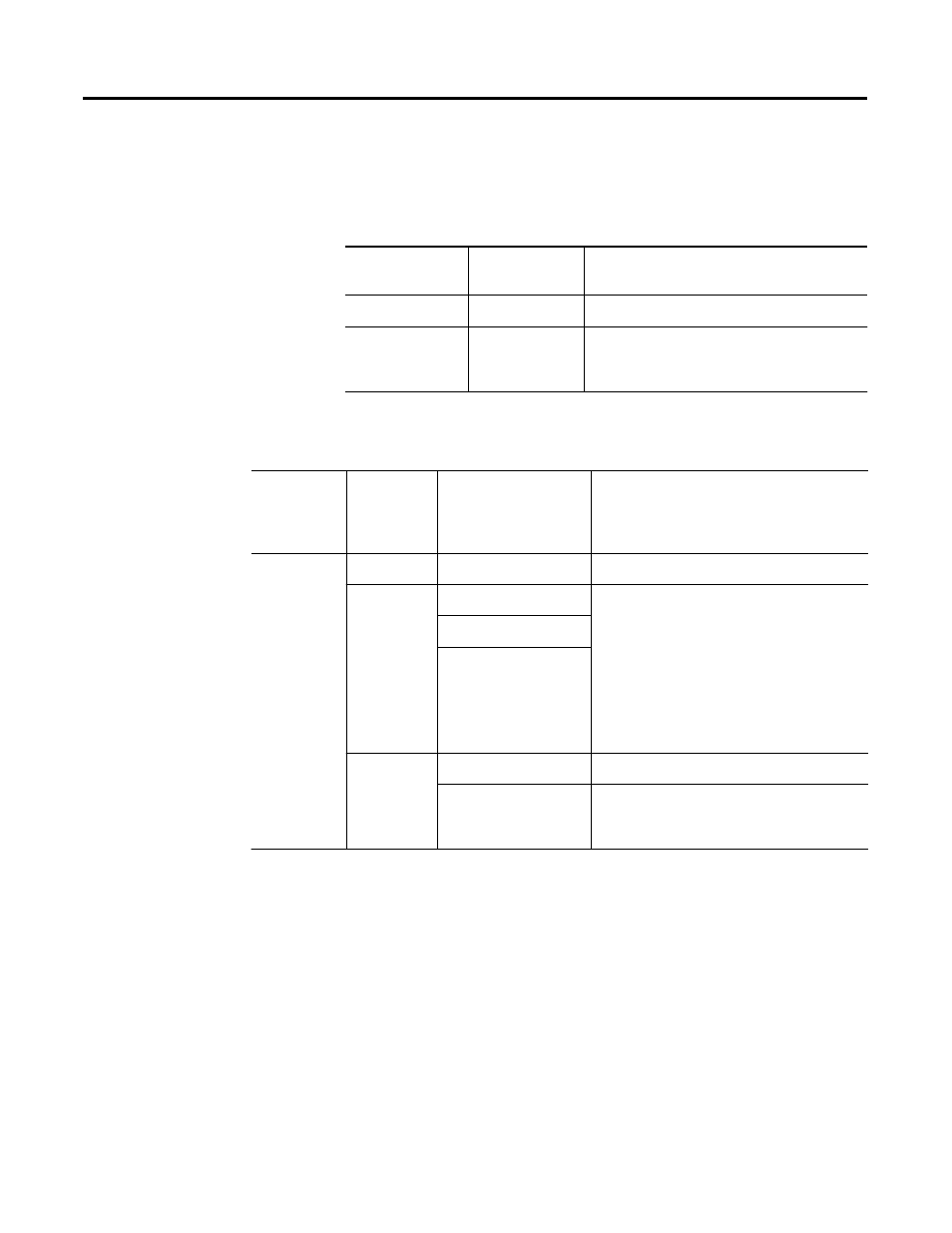
If Module Status
LED is:
Indicated
condition:
Corrective action:
On
Proper Operation
No action required.
Off
Module Fault
Cycle power. If condition persists, call your
local distributor or Allen-Bradley for
assistance.
If Module
Status LED
is:
And
Channel
Status LED
is:
Indicated Condition:
Corrective action:
On
On
Channel Enabled
No action required.
Blinking
Open-Circuit Condition
To determine the exact error, check the error
bits in the input image bits (15 through 13).
Check the channel configuration word for
valid data. Make sure that the data format is
indicated correctly in status bits. Class 1 data
format status bits are bits 5 and 4. Class 3
data format status bits are bits 6-4. See the
“Troubleshooting Flowchart” on page 6-6 and
Chapter 5 for more information.
Out-of-Range Condition
Channel Configuration
Error
Off
Power-Up
No action required.
Channel Not Enabled
No action required. For an example showing
how to enable a channel, see Chapter 2,
Quick
Start, or Chapter 7, Application Examples.