Rockwell Automation 1746-NI16V SLC 500 Analog Input Modules User Manual User Manual
Page 22
Publication 1746-UM001A-US-P
2-8 Quick Start for Experienced Users
9.
Go through the system start-up procedure.
Reference
Apply power. Download your program to the SLC 500 processor and put the controller into Run mode. During
a normal start up, the module status LED and any enabled channel status LED turn on.
Chapter 6
(Module Diagnostics and
Troubleshooting)
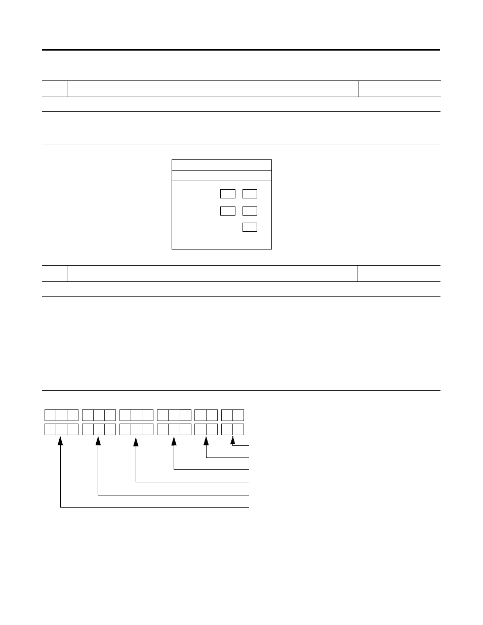
Channel
Status LEDs
Module Status LED
ANALOG MODULE
INPUT
0-3
4-7
8-11
12-15
10.
Check that the module is operating correctly.
Reference
(Optional) If the Module Status LED is off, or if the Channel 0 LED is off or blinking, refer to Chapter 6.
Class 3 Interface - Monitor the status of input channel 0 to determine its configuration setting and
operational status. This is useful for troubleshooting when the blinking channel LED indicates that an error
has occurred. The example below shows the Class 3 status word for channel 0 with no errors.
Chapter 5
(Channel Configuration,
Data and Status)
Chapter 6
(Module Diagnostics and
Troubleshooting)
Chapter 7
(Application Examples)
12
4
15
14
13
11
10
9
8
7
6
5
3
2
0
0
1
1
1
1
0
0
0
0
0
0
0
0
1
0
0
0
Bit Number
Channel 0 Status Word (I:1.8)
•
Data Format
•
Calibrate Channel Status
•
Filter Frequency
•
Error Conditions
•
Class 1 Data or Status Configuration
•
Input Type