Module installation procedure, Module removal procedure – Rockwell Automation 1746-NI16V SLC 500 Analog Input Modules User Manual User Manual
Page 30
Publication 1746-UM001A-US-P
3-8 Installation and Wiring
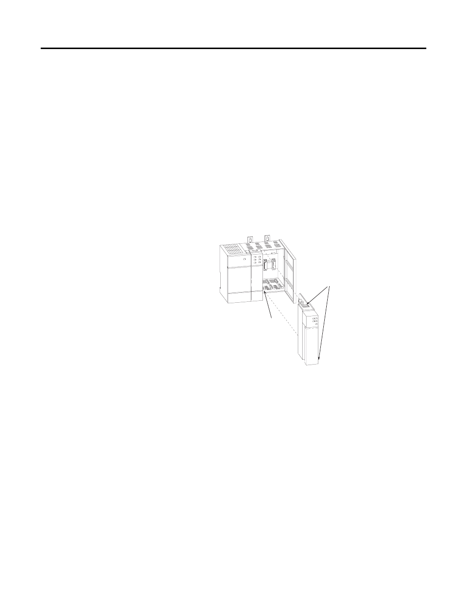
Module Installation Procedure
1. Read the “Module Location in Chassis” section beginning on
2. Align the circuit board of the analog input module with the card
guides located at the top and bottom of the chassis.
3. Slide the module into the chassis until both top and bottom
retaining clips are secured. Apply firm, even pressure on the
module to attach it to its backplane connector. Never force the
module into the slot.
4. Cover all unused slots with the Card Slot Filler, catalog number
1746-N2.
Module Removal Procedure
1. Press the releases at the top and bottom of the module and slide
the module out of the chassis slot.
2. Cover all unused slots with the Card Slot Filler, catalog number
1746-N2.
Card
Guide
Top and Bottom
Module Release(s)