Rockwell Automation 1771-ACNR15 CONTROLNET ADAPTER MODUL User Manual
Page 33
3–9
Addressing Modes for Your I/O
Publication 1771-6.5.124 – August 1997
I/O Module Combinations
The combination of I/O modules you can use depends on the
addressing method and I/O chassis you select.
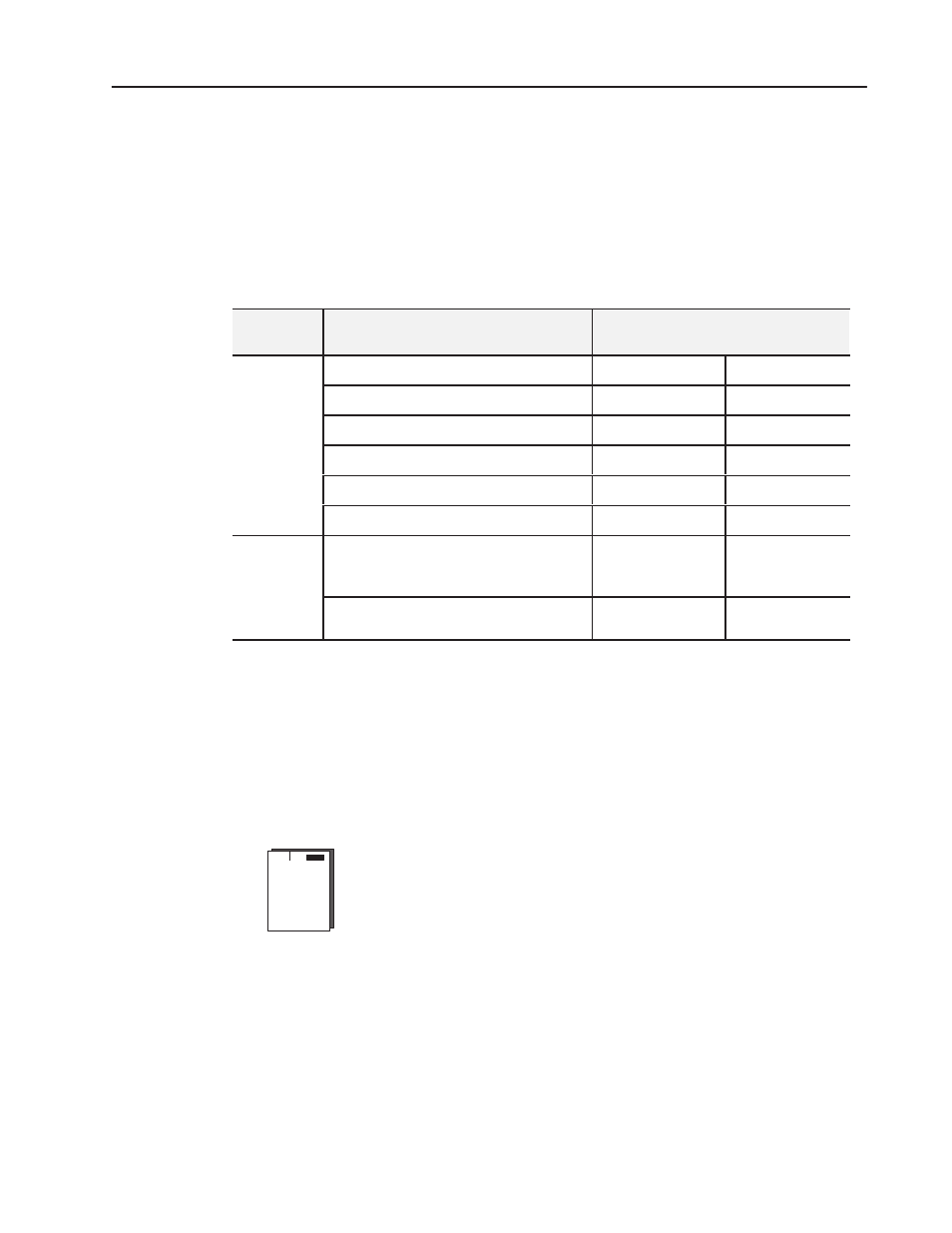
The table below lists acceptable I/O module combinations with 1-slot
addressing.
Table 3.B
I/O Module Combinations With 1-slot Addressing
I/O Chassis
Series
I/O Module Combinations Per I/O Group
Data Table Bits Used
Input Image Table Output Image Table
A, B
1 8-point input module
8
0
1 8-point output module
0
8
1 8-point input and output module
8
8
1 8-point input and 1 nondiscrete output module
16
8
1 nondiscrete input and 1 8-point output module
8
16
1 nondiscrete module
8
8
B or later only
any mix of 8, 16 and 32-point input and output
modules (when using 32 point modules, install in
pairs – input and output in each group)
16
16
any mix of 8 and 16-point modules, and
nondiscrete or intelligent modules
16
16
Using 1/2- Slot Addressing
Definition: The processor addresses one-half of an I/O module slot as
one I/O group.
Concept: The physical address of each I/O slot corresponds to two
input and two output image table words. The type of module you
install (8-, 16-, or 32-point) determines the number of bits in these
words that are used.
You select 1/2-slot addressing by setting switches 5 and 6 of the I/O
chassis backplane switch assembly as shown in Chapter 2:
•
switch 5 to the OFF position
•
switch 6 to the ON position
With 1/2-slot addressing, since 32 inputs bits AND 32 output bits are
available in the processor’s image table for each I/O group, you can
mix 8-point, 16-point, 32-point and nondiscrete modules in any order
in the I/O chassis.