Rockwell Automation 1771-ACNR15 CONTROLNET ADAPTER MODUL User Manual
Page 21
2–7
Installing Your ControlNet Adapter Module
Publication 1771-6.5.124 – August 1997
!
ATTENTION: Do not force the module into the
backplane connector. If you cannot seat the module
with firm pressure, check the alignment and keying.
Forcing the module can damage the backplane
connector or the module.
5. Snap the chassis locking bar (or locking latch on earlier chassis)
over the top of the module to secure it. Make sure the locking
pins on the locking bar are fully engaged.
Note: The chassis locking bar will not close if all modules are not
properly seated.
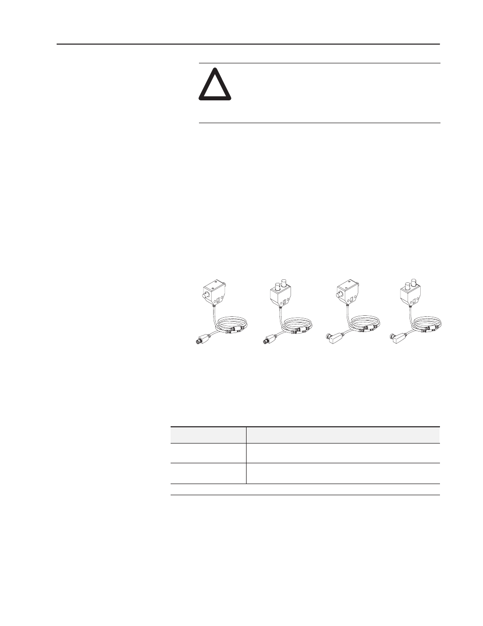
Connecting Your Adapter to the ControlNet Network
You connect your 1771-ACN15 or -ACNR15 adapter module to a
ControlNet network via taps. These taps are available:
Straight T-tap
Straight Y-tap
Right-angle T-tap
Right-angle Y-tap
1786-TPS
1786-TPYS
1786-TPR
1786-TPYR
Important: Taps contain passive electronics and must be purchased
from Allen-Bradley for the network to function
properly.
1. Remove the tap’s dust cap (located on the straight or right
angle connector).
If your node supports: Connect the tap’s straight or right angle connector:
Non-redundant media
to the channel A connector on the 1771-ACN15 or 1771-ACNR15
(channel B on the 1771-ACNR15 is not used)➀
Redundant media
•
from trunkline A to channel A on the 1771-ACNR15
•
from trunkline B to channel B on the 1771-ACNR15
➀
While both channels are active, Allen-Bradley recommends using channel A for non-redundant media.