Diagnostic indicators, Communication reset pushbutton, Network access port (nap) – Rockwell Automation 1771-ACNR15 CONTROLNET ADAPTER MODUL User Manual
Page 12
1–2
Introducing the ControlNet Adapter Module
Publication 1771-6.5.124 – August 1997
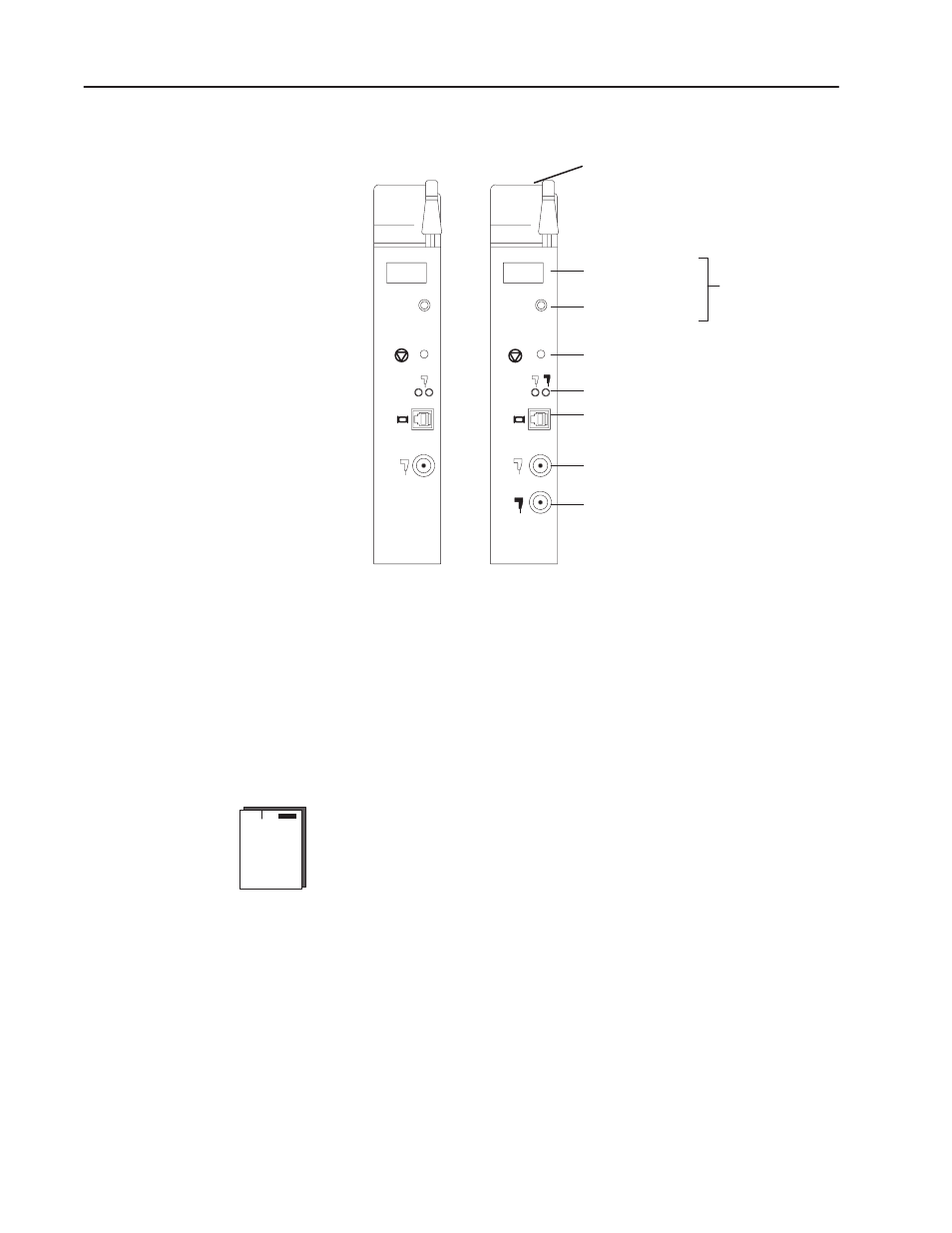
Figure 1.1
ControlNet Adapter Module
Diagnostic Indicators
Communication Reset Pushbutton
ControlNet Status Indicators
ControlNet Redundant Media Port
(1771-ACNR15 only)
ControlNet Media Port
Network Access Port (NAP)
1771-ACN15
1771-ACNR15
Status Display and
Net Address
STATUS
NET
ADDRESS
A
ALLEN-BRADLEY
1771-ACN15
ALLEN-BRADLEY
1771-ACNR15
B
A
STATUS
OK Indicator
Module Network Address Switches
(accessible thru top of module)
OK
OK
NET
ADDRESS
Diagnostic Indicators
The OK indicator is located on the front panel of the adapter module
(Figure 1.1). It shows both normal operation and error conditions in
your remote I/O system.
In addition, an alphanumeric display (net address/status) provides
status code indications when an error occurs during initialization or
operation.
A complete description of the diagnostic indicators and status display
and how to use them for troubleshooting is explained in chapter 5.
Communication Reset Pushbutton
This pushbutton is active whenever the status display shows RSET
or PRL. PRL is active only when the I/O chassis backplane switch is
in the PRL position. If the above conditions are met, you can use the
reset pushbutton (Figure 1.1) to reset the adapter module and resume
communication after a communication error occurs.
Network Access Port (NAP)
The network access port (Figure 1.1) provides a bidirectional
electrical interface for programming, maintenance, and I/O