Rockwell Automation 1771-ACNR15 CONTROLNET ADAPTER MODUL User Manual
Page 20
Y
N
N
Y
USING
POWER SUPPLY
MODULE IN
THIS CHASSIS?
I/O Chassis
Power Supply
Configuration
Plug
Y N
front of chassis
locking-bar pins
12453-I
2–6
Installing Your ControlNet Adapter Module
Publication 1771-6.5.124 – August 1997
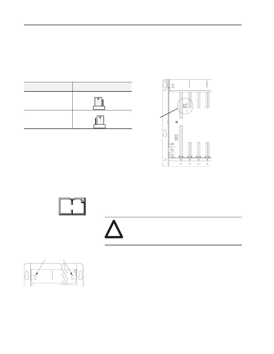
Set the I/O chassis power-supply configuration plug (Figure 2.4) to
identify the type of power supply you are using with your remote
chassis. This configuration plug is located on the backplane of
1771-A1B through -A4B or later I/O chassis.
Figure 2.4
1771 I/O Chassis Power Supply Configuration Plug Settings
For Use With:
Set Chassis Configuration Plug to:
power supply module installed
in chassis
“Y” position
external power supply in your
remote system
“N” position
Once you’ve determined the power requirements and keying for your
adapter module, and have set the appropriate switch assemblies, you
can use the following procedure to install it.
Refer to the Industrial Controller Wiring and Grounding Guidelines
(publication 1770-4.1) for proper grounding and wiring methods to
use when installing your module.
!
ATTENTION: Remove system power before
removing or installing your module in the I/O chassis.
Failure to observe this warning could damage module
circuitry and injure people.
1. Remove power from the I/O chassis before inserting (or
removing) the module.
2. On chassis equipped with a chassis locking bar, pull the
locking-bar pins to release the locking bar and swing it up. If
installing in an earlier chassis, lift the module locking latch up.
3. Place the module in the plastic tracks on the top and bottom of the
leftmost slot. These tracks guide the module into position.
4. Press firmly and evenly to seat the module in its backplane
connectors.
More
Setting the I/O Chassis
Power Supply
Configuration Plug
Installing the Adapter
Module in the Chassis