Select and launch the enter g data icon. a, Length of g file at 94 words – Rockwell Automation 1746-MPM INSTALL INSTRUC MOLD PRESSURE User Manual
Page 9
Mold Pressure Module
9
Publication 1746-5.13 July 1998
4.
Select the Adv Configuration icon and launch it. Then select/enter:
A.
Length of M0/M1 files at 106 words, each (listed in section 11).
B.
Length of G file at 94 words.
5.
Select and launch the Enter G Data icon.
A.
Change the display radix to hex. You get this display:
B.
Select word one (as shown) and enter the bit-selected data word that
corresponds to the module’s configuration in your application. You
determine the equivalent hex value of this word in next section
.
G-file Configuration (Initial Hardware Configuration)
The module requires software-configured selections in G file word 1.
You may set bits by entering an equivalent bit-set word in hex
%
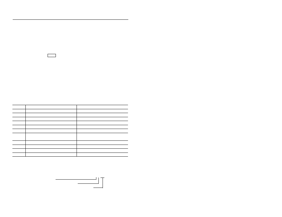
For example, from tables that follow, a hex value of F200 represents:
Bit
Purpose
Selection
00-02
reserved
n/a
03
Chnl 1 source of data
0 = sensor, 1 = SLC output image table
04
Chnl 2 source of data
0 = sensor, 1 = SLC output image table
05-08
reserved
n/a
09
Trigger Operation
0 = triggers, 1 = no triggers
10
channel 1 & 2 alarms turned off by T4
0 = no, 1 = yes
11
Channel 1 & 2 alarms go OFF when T4
(mold closed) trigger does the following:
0 = goes ON (at mold close),
1 = goes OFF (at mold open)
12
Channel 1 sensor level
0 = high, 1 = low (must match jumpers)
13
Channel 2 sensor level
0 = high, 1 = low (must match jumpers)
14
Alarm operation
0 = alarms, 1 = no alarms
15
module reset
1 = set (required)
F200
Senser level = high for both channels, and alarms = off
(bits 15-12 = 1 1 1 1 = F)
Triggers and T4 = off (bits 11-08 = 0 0 1 0 = 2)
Data source = from sensors for both channels (bits 07-00 = 0)
0
404
0
0
0
0
5
0
0
0
0
0
10
0
0
0
0
0
:
:
:
:
:
:
90
0
0
0
0
0