Select gain and zero-reference with jumper plugs, Important – Rockwell Automation 1746-MPM INSTALL INSTRUC MOLD PRESSURE User Manual
Page 7
Mold Pressure Module
7
Publication 1746-5.13 July 1998
Pressure values transferred from the SLC data table to the module must be
integer numbers in units of PSI. If using the Pro-Set 200 Injection Control
System, the ladder logic provides pressure values in the correct format.
4. Configure the module with jumper plugs
Each channel is independently configurable. Jumper-plug configurations
selected here must match G-file bit selections done next in section 5.
The module’s default channel input configurations are:
•
channel 1: mold pressure sensor (low-level) connected to the module
•
channel 2: injection pressure sensor (high-level) connected to module
You may use these default configurations or change them as needed.
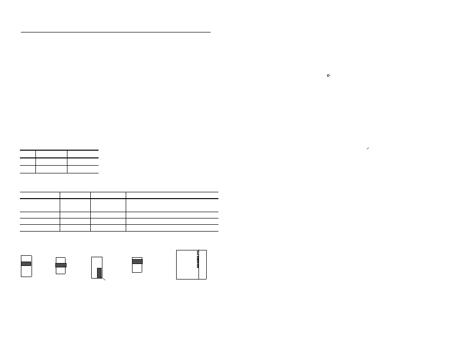
Select gain and zero-reference with jumper plugs
Important:
For a 5% FS zero reference, a 2mv/V sensitivity and gain of
450 give an amplified 9.0V operating range of 0.5-9.5V dc. This lets the
module and software continuously autozero the lo-end signal for variations
due to pre-load and/or changes in temperature.
Chnl
Gain Jmpr
0-ref Jmpr
1
JP5 @ 450
JP1 @ 5%FS
2
JP6 @ 1 (NC)
JP2 @ 0V
For this sensor
Select Gain:
Select 0- ref:
Notes:
lo-level (2mV/V)
450
5% FS
(see Important)
Gain settings of 250 and 100 are available for
sensor sensitivities of 6 and 9 mV/V.
lo-level (4-20mA)
1
0V
For 4-20mA sensors, set channel to hi-level.
bi-directional (±)
450
mid point
For sensor outputs such as -100 to +100mV
hi-level (0-10V)
1
0V
For gain = 1 (NC), store jumper as shown.
JP5 Gain
JP6 Gain
JP1 0-ref
JP2 0-ref
- 0V
- 5% FS
- mid pt
- 0V
- 5% FS
- mid pt
- 4-20mA
- 450
- 250
- 100
- 1 (NC)
- 4-20mA
- 450
- 250
- 100
- 1 (NC)
- 4-20mA
- 450
- 250
- 100
- 1 (NC)
- 4-20mA
- 450
- 250
- 100
- 1 (NC)
- 4-20mA
- 450
- 250
- 100
- 1 (NC)
- 4-20mA
- 450
- 250
- 100
- 1 (NC)
Channel 1 Default Jumpers
Channel 2 Default Jumpers
* *
* *
* *
* *
* *
* *
* *
* *
* *
* *
* *
Jumper Locations
JP6
JP2
JP5
JP1
Module
For a gain of 1 (NC), rotate jumper and store as shown.