Select the calibration resistor with jumper plugs – Rockwell Automation 1746-MPM INSTALL INSTRUC MOLD PRESSURE User Manual
Page 8
8
Mold Pressure Module
Publication 1746-5.13 July 1998
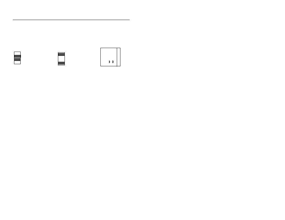
Select the calibration resistor with jumper plugs
Select the module’s internal calibration resistor or external resistor located
in the sensor or separately wired to the module’s terminal block.
5. Configure the SLC Processor (including I/O, M0/M1, and G file)
This procedure is based on RSLogix500 programming software, version
2.0 or later. For other software, the procedure may vary.
Configure the SLC processor, I/O, size of M0/M1 files, and G file offline
to match your system layout.
1.
With the File pull-down window, open the ladder file associated with
this project, or create a project (ladder file) for it.
2.
If you have not already done so, select the Controller Properties icon
and launch it. Then select/enter the type of SLC processor.
3.
Select the I/O Configuration icon and launch it. Then select/enter:
A.
Slot number in the I/O chassis for this module
If using this module in a Pro-Set 200 Injection Control System,
assign this module to slot 7.
B.
Module ID (12935), entered under “Other” in the I/O Module window.
Important:
When you enter the module ID, the processor automatically
reserves the required number of I/O image table words. The location of
those words in the I/O image table is determined by the module’s slot
location in the I/O chassis. Slot location is a required addressing unit.
For example, I:e.6 locates the 6th word in the block of input image table
words assigned to the module in slot e that you entered in A, above.
C.
If you have not already done so, enter the size of I/O chassis and the type
of power supply.
JP3 Cal Res
JP4 Cal Res
Channel 1 Jumper
Channel 2 Jumper
* *
* *
* *
* *
* *
Jumper Locations
Module
JP3 JP4
* *
Internal 200K
default position
External