Dc, - dc, M1, m2, m3, Connect the motor leads to these terminals – Rockwell Automation 1336VT 5-300 AMP (2.2-160KW) User Manual
Page 58
Wiring
Chapter 6
6-14
+DC
-DC
M1
M2
M3
L1
L2
L3
USE 755C COPPER WIRE ONLY
WIRE RANGE 350 MCM - 6 AWG
TIGHTENING TORQUE 275 INCH
POUNDS
USE 755C COPPER WIRE ONLY.
WIRE RANGE 500 MCM - 0 AWG
TIGHTENING TORQUE 375 INCH
POUNDS
jA
jB
jC
jA
jB
jC
❶
❶
❶
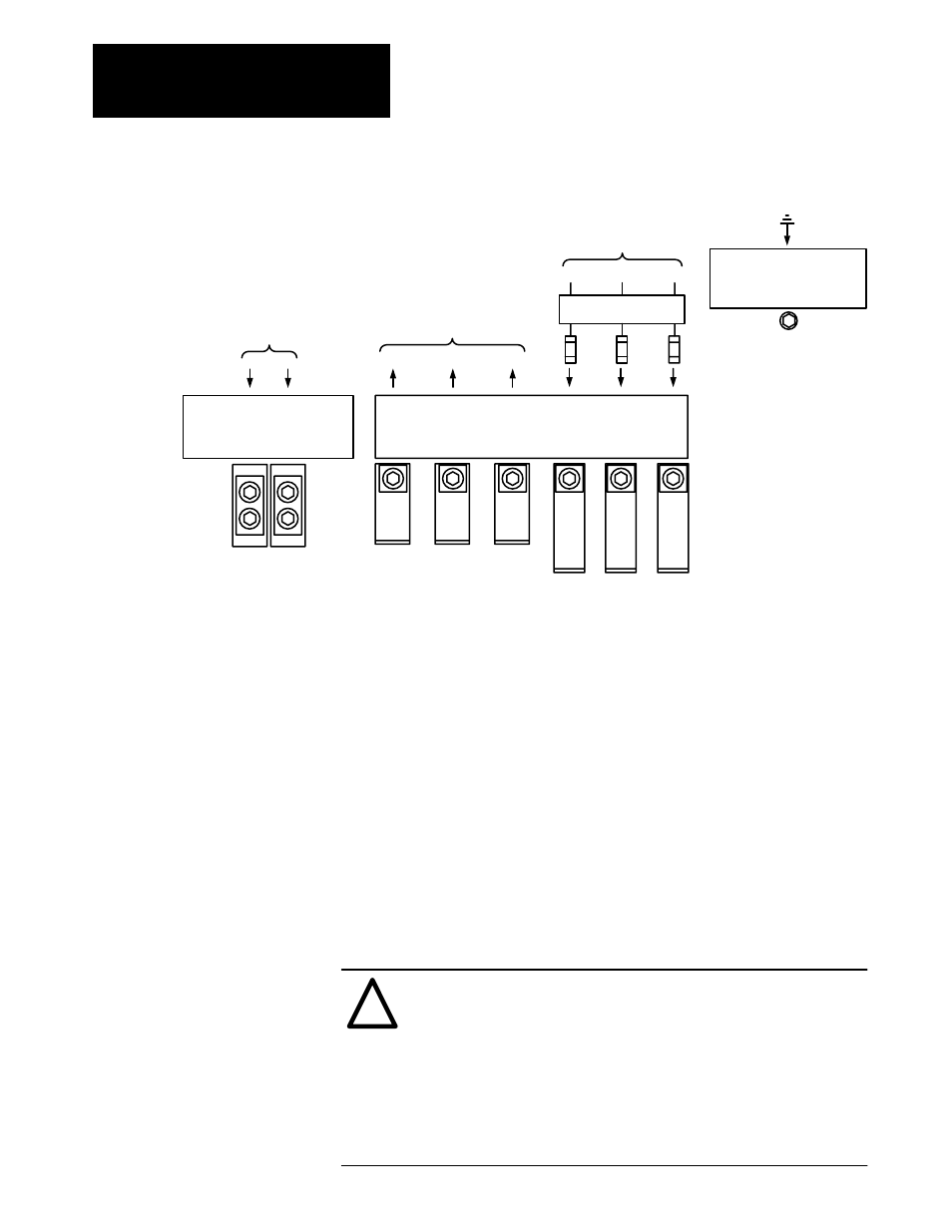
Terminal Block TB1 -
240Ć300ĂAmp Power Wiring
Motor
AC Incoming Line
1336
Dynamic
Brake
Earth
Ground
USE 755C COPPER WIRE ONLY
WIRE SIZE 2 (3) AWG
TIGHTENING TORQUE 275 INCH POUNDS
GND
❷
❶
User supplied drive input fuses.
❷
Motor disconnecting means including branch circuit, short circuit, and ground fault protection.
GND
Chassis ground is used to connect the drive chassis to a common ground.
The motor frame must also be connected to the same common ground.
Either earth ground or the ground of the building system must be used.
Refer to the motor manufacturer’s guidelines for additional information.
+ DC, - DC
DC bus terminals are reserved for the 1336 dynamic brake option. Refer to
the 1336 dynamic brake option instructions for installation and connection
details.
M1, M2, M3
Connect the motor leads to these terminals.
!
ATTENTION: A hazard of potential damage to drive output
power components exists if there is insufficient load inductance to
permit the drive short circuit protection function to be effective.
Sufficient load inductance is provided by one of the following:
•
Option 1336-MOD-LR.
•
Load reactors of 10mH connected to each motor lead.
•
Motor leads with a minimum length of 40 feet (12.2 meters)
between the drive and the motor.