Power module check, Step 5. press the, Key to clear the log – Rockwell Automation 1302 575v AC Drive - Canada Only User Manual
Page 85
9–7
Troubleshooting
Publication 1302-5.0 — January, 1998
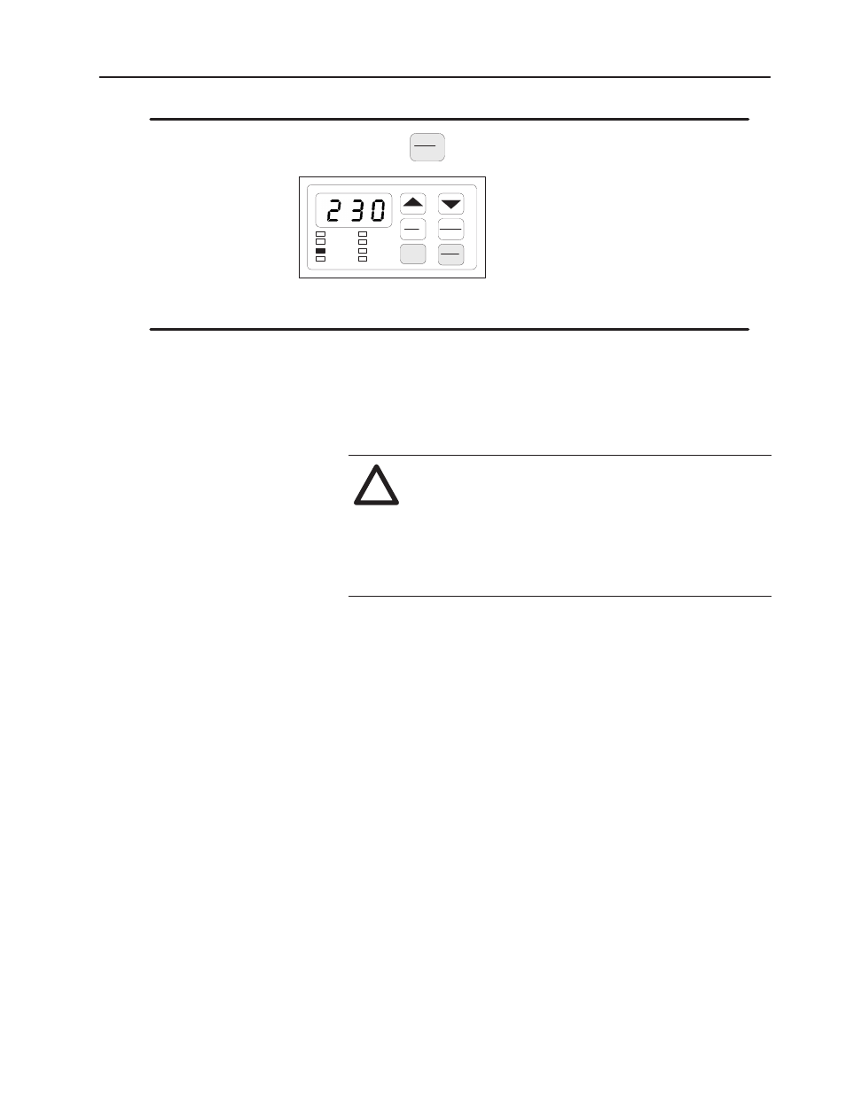
Step 5.
Press the
STOP
RESET
key to clear the log.
Mode
Enter
START
Forward
Reverse
STOP
RESET
RPM
%Load
Volts
Remote
RUN
Program
Forward
Reverse
The display will return to the active monitor display.
If a fault occurs, the Drive displays a fault code and logs the fault
code into the error log. If more than one fault occurs, the first fault
flashes on the display and the subsequent faults (up to two) are
logged in the error log. After three faults, no subsequent faults are
logged.
!
ATTENTION: DC bus capacitors retain hazardous
voltage after input power has been disconnected.
Disconnect and lock out power to the Drive and wait
five (5) minutes for the DC bus capacitors to discharge.
Failure to disconnect power could result in death or
serious injury. Verify bus voltages using the procedure
in Chapter 9 before beginning any checks.
Use the following procedure to check the Drive’s Power Module
circuitry. Note that this test is performed with the power off.
Step 1. Turn off and lock out input power. Wait five minutes.
Step 2. Remove the Drive’s cover.
Step 3. Verify that there is no voltage at the Drive’s input power
terminals
Step 4. Check the DC bus voltage with a voltmeter as described in
Chapter 9 to ensure that the DC bus capacitors are
discharged.
Step 5. Disconnect the motor from the Drive.
Step 6. Check all AC line and DC bus fuses.
Step 7. If a fuse is open, use a multimeter to check the input diodes
and output IGBTs. See Tables 9.B and 9.C
.
Step 8. Reconnect the motor to the Drive.
Step 9. Reattach the Drive’s cover.
Step 10. Reapply input power.
Power Module Check