Rockwell Automation 440R MSR300 Modular Safety Control System User Manual
Page 56
MSR300 Safety System Manual
Rockwell Automation
MSR300 Manual.doc
Pg 56 of 85
Vibration and mechanical shock:
The MSR300 modules must not be subjected to vibration or mechanical in excess of the
specified limits (in accordance with IEC 68 part: 2-6/7):
Vibration:
10 – 55 Hz, 0.35 mm
Mechanical shock:
10g, 16 msec, 100 shocks
7.2.3 Electrical
For planning information, refer to the guidelines in the document "Industrial Automation
Wiring and Grounding Guidelines" (Allen Bradley Publication 1770-4.1).
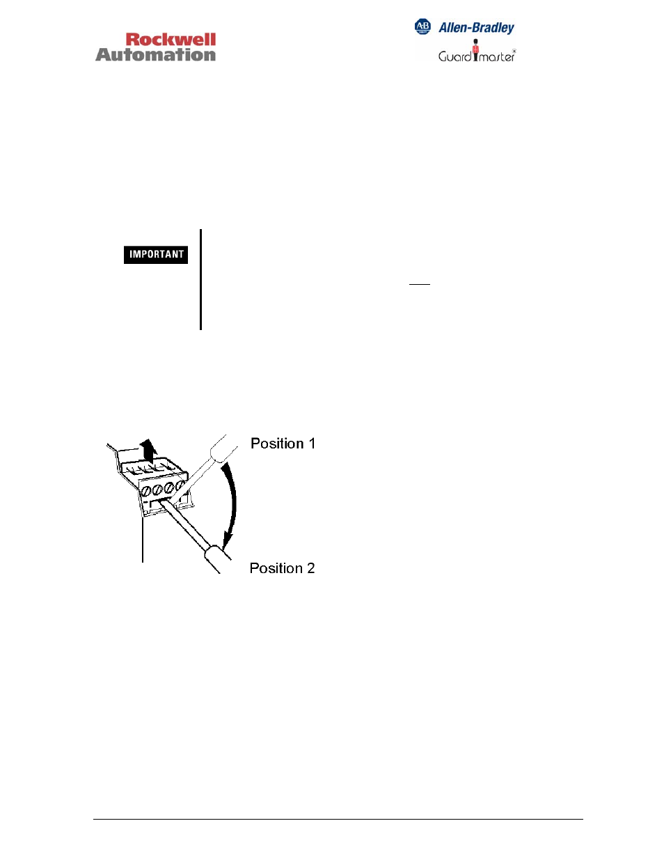
Removing the terminal blocks:
Make sure that electrical power supply to MSR300 System is switched off before making
or removing any electrical connections,
Connecting wires should be installed so that no mechanical forces (e.g., mechanical
tension) are transmitted through them to the modules, particularly the terminals.
Tighten all terminal screws firmly (*) and re-check all after connections have been made.
(* Recommended screw-tightening torque: 0.6 to 0.8 Nm or 5 to 7 lb-in).
Suitable arc and spike suppression components must be connected across load devices
of switching outputs (electromechanical contacts or solid-state switch) where the load
devices are inductive or capacitive.
• To remove the terminal
block, insert the screw driver
in position 1and then move it
slowly to position 2. For the
lower terminal blocks, the
action will be in the reverse
direction
The external power supply unit for the MSR300 System must
conform to the Directive 73/23/EEC Low Voltage, by applying the
requirements of EN 61131-2 Programmable Controllers, Part 2 -
Equipment Requirements and Tests, and one of the following:
• EN 60950 - SELV (Safety Extra Low Voltage)
• EN 60204 - PELV (Protective Extra Low Voltage)
• IEC 60536 Safety Class III (SELV or PELV)