Rockwell Automation 440R MSR300 Modular Safety Control System User Manual
Page 22
MSR300 Safety System Manual
Rockwell Automation
MSR300 Manual.doc
Pg 22 of 85
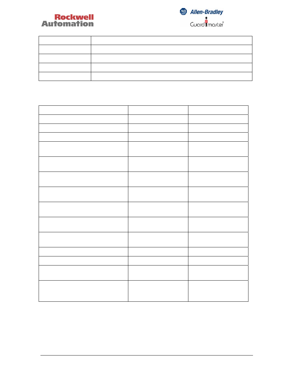
Y40, Y41, Y42
Reset configuration
S34
Start button
Y31 – Y33
Solid-state auxiliary outputs for groups 1, 2 and 3
Y10
+24V for reset circuit and feedback loops
Y11 – Y13
Feedback loop inputs for Groups 1, 2 and 3
4.1.2 LED Indicators
Function
Status LED
Group 1-2-3 LEDs
Power up / normal operation
Continuous on: green
---
Internal fault
Continuous on: red
---
Entering configuration mode
1 flash: red
---
Input switch fault or reset switch
closed during power up
2 flashes; red
---
Configuration change during
operation
3 flashes; red
---
Current configuration not as stored
on EEPROM
4 flashes; red
---
At least one muting lamp and one
reserve lamp defective
5 flashes; red
---
Invalid switch settings of input
modules
6 flashes; red
---
Invalid reset configuration (Y41,
Y42, S34 terminal jumpers)
7 flashes; red
---
Input terminal block not (or
improperly) plugged in
8 flashes; red
---
Group output active
---
Continuous on: green
Group ready
---
Blinking: green
At least one input corresponding to
the output group is faulty
---
Continuous on: red
A feedback (EDM) loop of the
output group is open, or no input is
assigned to the group
--- Off
LEDs "TxD1" and "TxD2" indicate RS232 data communication activity when flashing.