Rockwell Automation 440R MSR300 Modular Safety Control System User Manual
Page 50
MSR300 Safety System Manual
Rockwell Automation
MSR300 Manual.doc
Pg 50 of 85
6.2
Recoverable Faults During Start-Up or Operation
Recoverable faults are also indicated by the "Status" LED, but by different flashing
patterns.
The various recoverable faults and their corresponding LED flashing patterns are
described below.
Note: Shut down power before corrective action (except Input switch fault). After
modification of configuration the set-up procedure as described in the next chapter is
required.
[In the LED Indication column, a number followed by "x" means that the LED flashes
(blinks) that many times, followed by a pause. The cycle repeats while the fault condition
exists.]
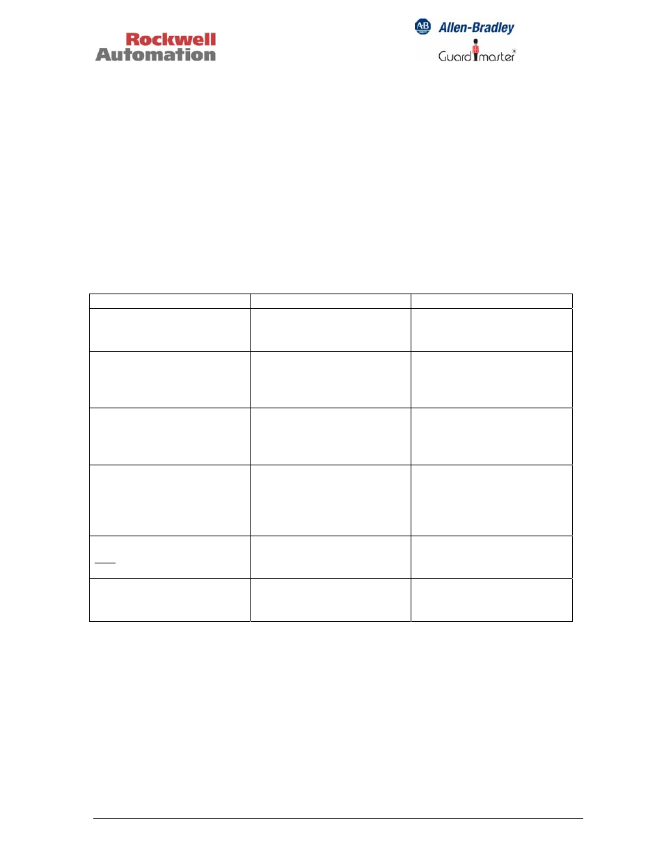
Fault Indication
Corrective
Action
Input switch fault (if switch
monitoring is enabled).
"Status" LED flashes 2 x.
LED of the faulty input
flashes, red.
Unlock the faulty input.
The reset pushbutton
(momentary switch) is
pressed while the system is
being powered up.
"Status" LED flashes 2 x.
Replace the reset switch.
Configuration changes
during operation.
(Terminals Y40, Y41, Y42,
S34).
"Status" LED flashes 3 x.
Check the jumpers at
terminals Y40, Y41, Y42,
S34.
The actual configuration
does not match what has
been previously stored in
EEPROM.
"Status" LED flashes 4 x.
Check the system
configuration. Reconfigure
as necessary, or have the
system read and store the
current configuration.
At least one muting lamp
and reserve lamp are
defective.
"Status" LED flashes 5 x.
Check and replace both
defective lamps.
Bus terminator plug of last
Input Module not (or
improperly) plugged in.
"Status" LED flashes 8 x.
Insert the bus terminator
plug.