Steriflow Mark 96A Series User Manual
Page 4
-4-
M
ark
96a S
anitary
a
ir
-L
oaded
P
reSSure
r
eguLator
m
aximum
i
nlet
P
ressure
vs
s
etPoint
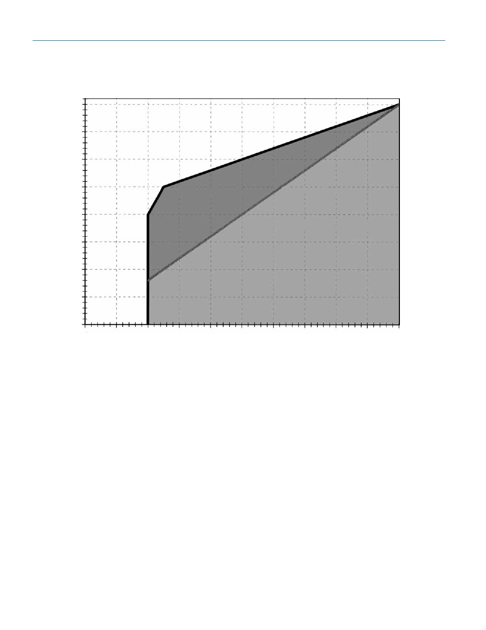
Determining Allowable & Optimal Setpoint
Reading the graph: To determine allowable setpoint select your inlet pressure from the Y-axis on the
above graph. Outlet pressure setpoint should be equal to or greater than the value on the X-axis
where the inlet pressure and heavy diagonal line intersect. In other words, the differential pressure
(between inlet pressure and outlet pressure setpoint) must be less than or equal to 100 psi. In addi-
tion the minimum outlet pressure setpoint is 20 psig.
For optimal results (minimum offset, more stability) the ratio of inlet pressure to the outlet pressure
setpoint (differential pressure) should be 2:1 or less, and never greater than 100 psig. For example,
if the inlet pressure is 150 psi, the allowable outlet pressure setpoint would be 50 psi or above.
However, the optimal outlet pressure setpoint (greater stability and less droop) is 75 psig or greater.
Note:
1. Valve actuator loading pressure (supply pressure) must be at least 3 psi above the desired
outlet pressure setpoint. This is needed to overcome the return spring bias.
Installation Notes
• As with all regulators and control valves, optimal flow performance can only be achieved with
a non-turbulent flow profile. The Mark 96A should be installed with 3 feet of straight pipe on either
side of the valve.
• A pressure gauge, or transmitter reading downstream of the Mark 96A should be used to make
the final setpoint adjustment.
200 (13,8)
175 (12,1)
150 (10,3)
125 (8,6)
100 (6,9)
75 (5,2)
50 (3,4)
25 (1,7)
0
0
10
(0,7)
20
(1,4)
30
(2,1)
40
(2,8)
50
(3,4)
60
(4,1)
70
(4,8)
80
(5,5)
90
(6,2)
100
(6,9)
Outlet Pressure Setpoint (psi (bar)
Maximum Inlet psi (bar)
Allowable Area
of Operation
Optimal Area of Operation