Prescolite 4W1ST User Manual
Ins tru ctio n s he et, Installation instructions 4w1, 4w1st trim
Ins
tru
ctio
nS
he
et
w
w
w
.p
r
e
s
c
o
li
te
.c
o
m
•P
res
co
lite
To
llF
ree
Te
ch
nic
al
Su
pp
ort
1.8
88
.P
RS
.4T
EC
•
Ho
urs
:8
am
-5
pm
ET
Part No. . . . . . . . . . . . . . . . . . . . . . . . . . . . . . . . .93005299
Ins
tru
ctio
nS
he
et
INSTALLATION INSTRUCTIONS
4W1, 4W1ST TRIM
IMPORTANT SAFETY INFORMATION. READ AND FOLLOW ALL SAFETY INSTRUCTIONS. Follow label information
and instructions concerning Wet or Damp Locations, installation near combustible materials, insulation, building materials,
and proper lamping. Do not install in areas subject to combustible vapors or gases. Before wiring to power supply and
during servicing or relamping, turn off power at fuse or circuit breaker. All servicing or relamping must be performed by
qualified service personnel. Product must be grounded to avoid potential electric shock or other potential hazard.
Product must be mounted in locations and at heights and in a manner consistent with its intended use, and in
compliance with the National Electrical Code and local building codes. The use of accessory equipment not
recommended by the manufacturer or installed contrary to instructions may cause an unsafe condition. Do not block light
emanating from product in whole or part, as this may cause an unsafe condition. Do not allow items such as drapes,
curtains, screens or the like to come into contact with the product or to block light from the product, as this may cause an
unsafe condition.
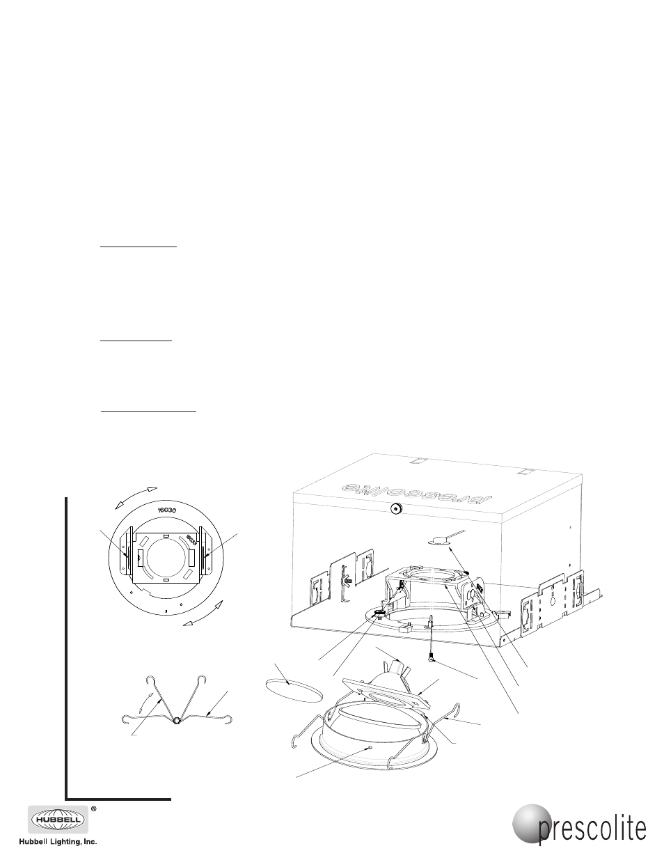
A. Lamp Installation:
1. Loosen horizontal and vertical locking Thumb Screws (1) & (2) and rotate Lamp Mounting Plate (3) to 0
degrees vertical. Rotate vertical locking thumbscrew clockwise and lock Lamp Mounting Plate into place in
this position.
2. Install lamp into Socket. (4)
3. Install Lamp (5) into Lamp Holder Bracket (6).
NOTE: If diffused lens (7) is required, install between (5) and (6).
B. Trim Installation:
1. Remove screw (10), pull Safety Cable (7) through opening in Plaster Frame and attach to Trim as shown
using Screw (10).
2. Squeeze the two Torsion Springs (8) together and insert ends into slots on both Brackets (9) as shown.
3. Push Trim towards ceiling until springs force the Trim against the ceiling line.
C. Horizontal Adjustment:
1. Make final horizontal adjustment by holding outer flange on Trim and rotating horizontally.
NOTE: If necessary, pull the flange away from the ceiling slightly before rotating.
2. Pull Trim away from ceiling and tighten locking Thumb Screw (1) after adjustment.
6
8
3
1
7
2
4
9
10
7
5
LOCATE TRIM FEATURE AWAY
FROM SIDE WITH SAFETY CABLE
SQUEEZE TORSION
SPRINGS AS SHOWN
9
9
8
701 Millennium Boulevard • Greenville, SC 29607
With representatives offices in principal cities throughout North America.
Copyright 2007, 06/07 revision, All Rights Reserved - Printed in U.S.A.