Prescolite 4B1STAC User Manual
Instruction sheet, Prs.4tec
Instruction
Sheet
www
.prescolite.com
Prescolite T
ollFree T
echnical Suppor
t
1.888.PRS.4TEC
Hours: 8am - 5pm ET
701 Millennium Blvd, Greenville, SC 29607
With representatives offices in principal cities throughout North America.
Copyright 2008, 7/29/08 All Rights Reserved - Printed in U.S.A.
Part No ....................................................... 93017390
IMPORTANT SAFETY INFORMATION. READ AND FOLLOW ALL SAFETY INSTRUCTIONS. Follow label information and instructions concerning Wet or Damp
Locations, installation near combustible materials, insulation, building materials, and proper lamping. Do not install in areas subject to combustible vapors or gases.
Before wiring to power supply and during servicing or relamping, turn off power at fuse or circuit breaker. All servicing or relamping must be performed
by qualified service personnel. Product must be grounded to avoid potential electric shock or other potential hazard. Product must be
mounted in locations and at heights and in a manner consistent with its intended use, and in compliance with the National Electrical
Code and local building codes. The use of accessory equipment not recommended by the manufacturer or installed contrary to instructions may cause an
unsafe condition. Do not block light emanating from product in whole or part, as this may cause an unsafe condition. Do not allow items such as drapes, curtains,
screens or the like to come into contact with the product or to block light from the product, as this may cause an unsafe condition.
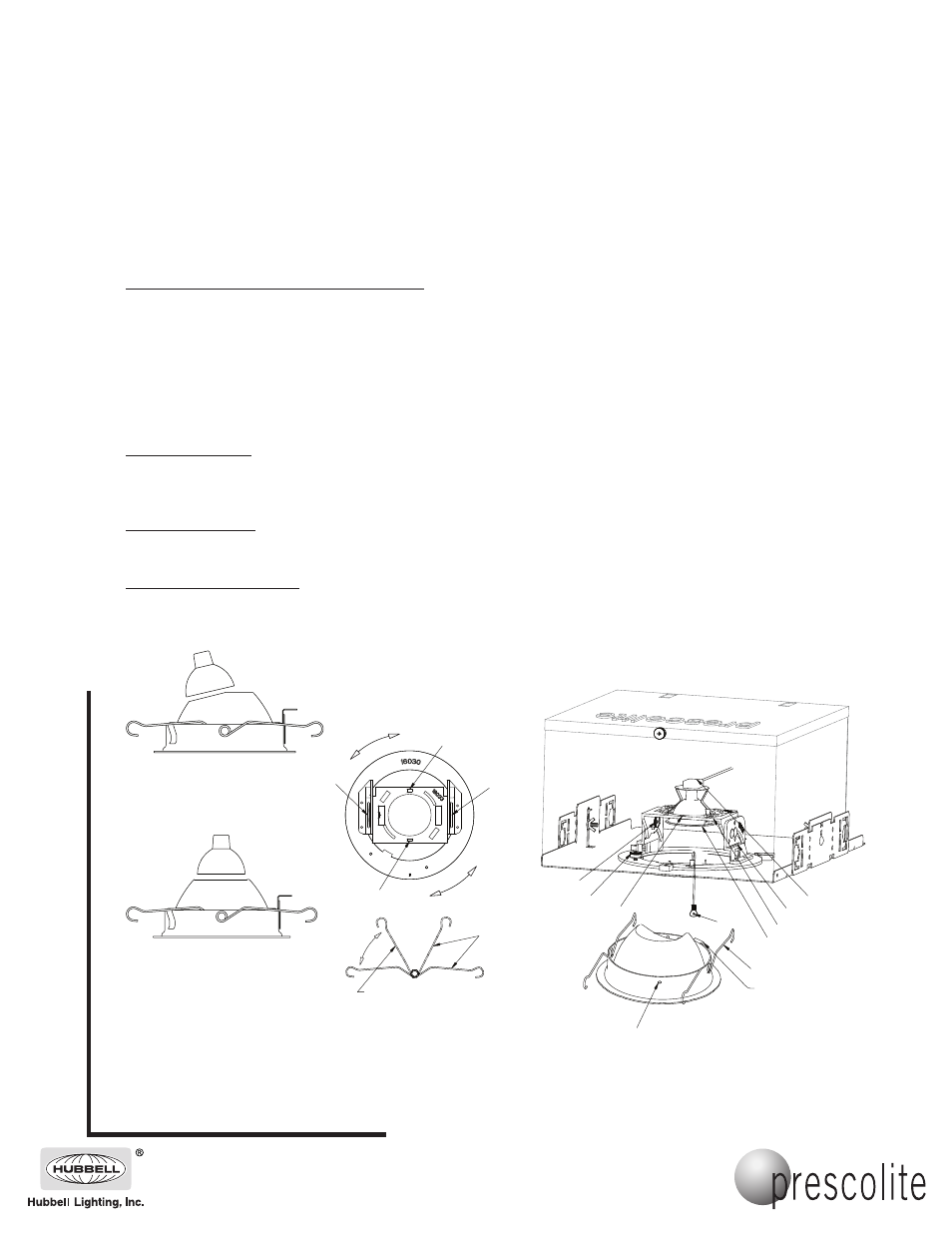
A. Lamp Adjustment Prior To Trim Installation:
1. Turn power off.
2. Loosen horizontal and vertical locking thumbscrews as shown. (1) and (2)
3. Remove Lamp Holder (3). Attach Socket (4) to Lamp. Make sure Lens Media is installed. Re-install lamp into Lamp Holder. Insert Lamp
Holder into Lamp Mounting Plate (5).
4. Rotate Lamp Adjusting Mechanism (6) to desired vertical angle and horizontal position by inserting a standard screwdriver into slots as
shown.(6) NOTE: Vertical increment indicator numbers can be used to pre-adjust the vertical angle if desired.
NOTE: Set lamp position at 0º for FC trims, or at specified angle shown on trim label for AC trims. Rotate
thumbscrew (2) clockwise to lock in place.
B. Trim Installation:
1. Remove Screw (10), pull Safety Cable (7) through opening in Plaster Frame and attach to Trim as shown using screw (10).
2. Squeeze the two Torsion Springs (8) together and insert ends into slots on both Brackets (9) as shown.
3. Push Trim towards ceiling until the Torsion Springs force the Trim against the ceiling line.
C. Final Adjustment:
1. Make final horizontal adjustment by holding outer flange on Trim and rotating horizontally.
NOTE: If necessary, pull the flange away from the ceiling slightly before rotating.
D. Locking Horizontal Aim:
NOTE: Turn power off and allow lamp to cool if necessary.
1. Pull Trim away from ceiling, reach into housing and rotate Thumb Screw (1) clockwise to lock in place.
2. Push Trim back towards ceiling until seated against ceiling.
INSTALLATION INSTRUCTIONS
4C1FC, 4B1FC, 4C1STFC, 4B1STFC
4C1AC, 4B1AC, 4C1STAC, 4B1STAC REFLECTOR
SQUEEZE TORSION
SPRINGS AS SHOWN
LOCATE TRIM FEATURE
AWAY FROM SIDE WITH
SAFETY CABLE
10
8
3
5
9
4
7
6
1
2
8
6
9
6
9
(ANGLE CUT)
AC
AC
(ANGLE CUT)
(FULL CUT)
FC
FC
(FULL CUT)
WARNING: This product contains chemicals known to the State of California to cause cancer, birth defects and/or other
reproductive harm. Thoroughly wash hands after installing, handling, cleaning, or otherwise touching this product.
CAUTION: DO NOT ATTEMPT TO MODIFY OR REWIRE FACTORY-INSTALLED WIRING ON THE FIXTURE. SAFETY
AND PROPER OPERATION OF THE FIXTURE DEPEND ON THE INTEGRITY OF THE WIRING.