Prescolite RHD801/02 User Manual
Instruction sheet, Installation instructions
Instruction
Sheet
www
.prescolite.com
• Prescolite
TollFree
Technical Support
1.888.PRS.4TEC
• Hours: 8am - 5pm ET
101 Corporate Drive • Spartanburg, SC 29303
With representatives offices in principal cities throughout North America.
Copyright 2004, 03/05 revision, All Rights Reserved - Printed in U.S.A.
Part No. . . . . . . . . . . . . . . . . . . . . . . . . . . . . . . . .06122400
Instruction
Sheet
INSTALLATION INSTRUCTIONS
CAT. NO. RHD601/02 & RHD801/02
Socket Holder
1.) Socket position is factory set for narrow distribution on all apertures; and for the wall wash with 6” trims.
To position socket for widest distribution: loosen locking screws, pull socket down until it stops, and then tighten screws to
lock position.
To position socket for regressed lens reflectors, and wall wash on the 8” reflector trims: remove stopping screw, loosen
locking screws, push socket up until it stops, and then tighten screws to lock position.
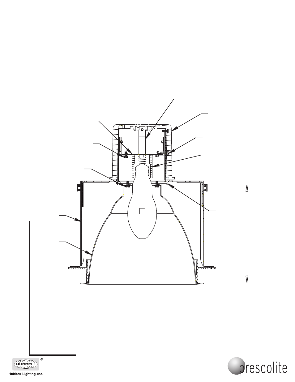
2.) For 8” regressed lens trims adjust the heatsink support bracket to 7 inches from finished ceiling surface.
For 6” regressed lens trims adjust the heatsink support bracket to 6 inches from finished ceiling surface.
For regressed lens trims, remove the lower trim before installing the upper trim.
3.) To install reflector, align keyhole slots in reflector top with reflector mounting screws located on the heatsink support bracket.
4.) Rotate the reflector as far as the keyway slots allow and tighten the mounting screws to draw the flange up against the ceiling.
Do not overtighten this adjustment as distortion of the reflector or damage to the baffle (for baffled reflectors) may occur.
5.) Install lower trim by inserting up through the plaster frame until flange is flush with ceiling.
RHD602 - 6”
RHD802 - 7”
For Lens
Trims Only
Heatsink
Support
Bracket
Socket
Socket Holder
Stop
Reflector
Stopping Screw
Socket Position
Locking Screw (2)
Support Riser
Heat Sink
IMPORTANT SAFETY INFORMATION. READ AND FOLLOW ALL SAFETY INSTRUCTIONS. Follow label information
and instructions concerning Wet or Damp Locations, installation near combustible materials, insulation, building materials,
and proper lamping. Do not install in areas subject to combustible vapors or gases. Before wiring to power supply and
during servicing or relamping, turn off power at fuse or circuit breaker. All servicing or relamping must be performed by
qualified service personnel. Product must be grounded to avoid potential electric shock or other potential hazard.
Product must be mounted in locations and at heights and in a manner consistent with its intended use, and in
compliance with the National Electrical Code and local codes. The use of accessory equipment not recommended by
the manufacturer or installed contrary to instructions may cause an unsafe condition. Do not block light emanating from
product in whole or part, as this may cause an unsafe condition. Do not allow items such as drapes, curtains, screens or
the like to come into contact with the product or to block light from the product, as this may cause an unsafe condition.
Reflector Mounting
Screw (2)