Prescolite 79XCP User Manual
Ins tru ctio n s he et, Installation instructions 79xcp
Ins
tru
ctio
nS
he
et
w
w
w
.p
r
e
s
c
o
li
te
.c
o
m
•P
res
co
lite
To
llF
ree
Te
ch
nic
al
Su
pp
ort
1.8
88
.P
RS
.4T
EC
•
Ho
urs
:8
am
-5
pm
ET
Part No. . . . . . . . . . . . . . . . . . . . . . . . . . . . . . . .124420100
Ins
tru
ctio
nS
he
et
INSTALLATION INSTRUCTIONS
79XCP
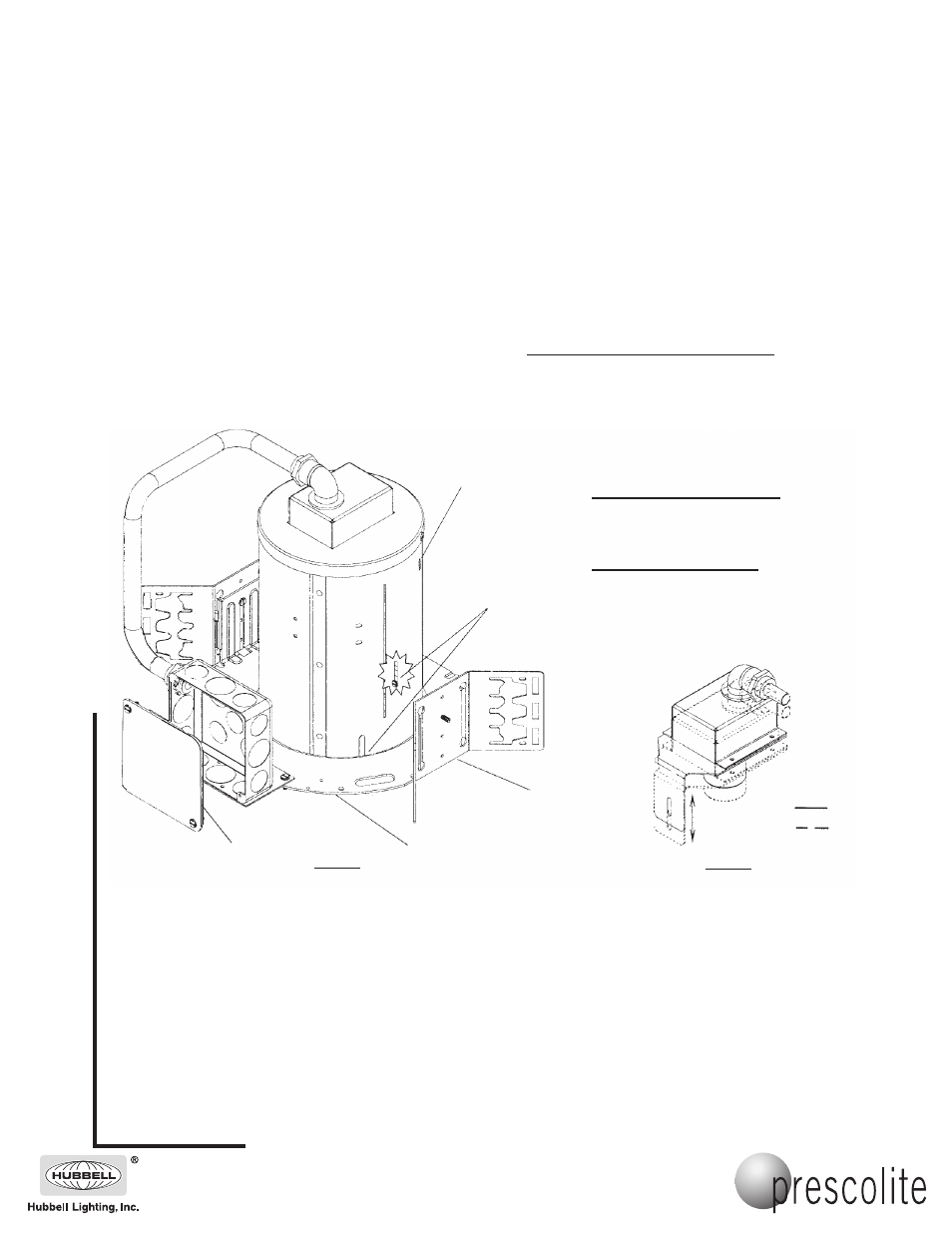
Housing
Plaster Flange
1. Install the fixture in the ceiling using mounting channel, bar stock or 1/2" rigid conduit placed in the adjustable mounting brackets.
The fixture should be installed in such a manner that the weight of the fixture is supported by the mounting channels/bar
stock/rigid conduit and/or hanger wires secured to the building structure.
2. Adjust the fixture so the bottom edge of the plaster flange is flush with the ceiling line by sliding the mounting brackets and secure
using adjusting screws (Fig. 1). Housing may be lowered further to compensatefor thick ceilings by use of the (3) thick ceiling
screws
3. Remove J-Box cover plate. Remove appropriate knockout and assemble appropriate connector for the supply wire used. Connect
ground wires to green ground leads. Connect white (common) to white (leads). Connect power supply (line) to black lead(s).
Reinstall J-Box cover.
WARNING: DO NOT pinch wires between J-Box/ballast cover and J-Box. Consult a Qualified Electrician for all other options
that require other wiring configurations.
CAUTION: DO NOT ATTEMPT TO MODIFY OR REWIRE FACTORY-INSTALLED WIRING ON THE FIXTURE. SAFETY AND
PROPER OPERATIONOF THE FIXTURE DEPEND ON THE INTEGRITY OF THE WIRING.
Figure 1.
Thick Ceiling
Adjustment
Screw (3)
PAR 38 LAMPS
J-Box Covers
Adjustable
Mounting Bracket (2)
PAR 38 LAMPS
Sl
id
e
Figure 2.
TRIM INSTALLATION (FIGURE 2):
1. ADJUST SOCKET BRACKET TO PROPER POSITION BY
LOOSENING WING NUT.
PAR 30 LAMPS: SLIDE BRACKET TO LOWEST
(TOWARDS APERTURE) POSITION.
PAR 38 LAMPS: SLIDE BRACKET TO HIGHEST
(AWAY FROM APERTURE) POSITION.
2. TIGHTEN WING NUT SECURELY.
ST832BB SERIES TRIMS:
3. INSTALL TRIM BY LOCATING COIL SPRINGS
IN SLOTS ON HOUSING.
4. INSTALL LAMP.
ST832 SERIES TRIMS:
3. INSTALL LAMP.
4. LOCATE TRIM CLIP RETAINING HOLES ON LIP
OF PLASTER FLANGE. ATTACH TRIM
RETAINING CLIPS (3) TO PLASTER FLANGE.
5. PRESS TRIM INTO APERTURE.
IMPORTANT SAFETY INFORMATION. READ AND FOLLOW ALL SAFETY INSTRUCTIONS. Follow label information
and instructions concerning Wet or Damp Locations, installation near combustible materials, insulation, building materials,
and proper lamping. Do not install in areas subject to combustible vapors or gases. Before wiring to power supply and
during servicing or relamping, turn off power at fuse or circuit breaker. All servicing or relamping must be performed by
qualified service personnel. Product must be grounded to avoid potential electric shock or other potential hazard.
Product must be mounted in locations and at heights and in a manner consistent with its intended use, and in
compliance with the National Electrical Code and local codes. The use of accessory equipment not recommended by
the manufacturer or installed contrary to instructions may cause an unsafe condition. Do not block light emanating from
product in whole or part, as this may cause an unsafe condition. Do not allow items such as drapes, curtains, screens or
the like to come into contact with the product or to block light from the product, as this may cause an unsafe condition.
701 Millennium Boulevard • Greenville, SC 29607
With representatives offices in principal cities throughout North America.
Copyright 2007, 02/07 revision, All Rights Reserved - Printed in U.S.A.