Prescolite CFQ/T EB/EBDMCP User Manual
Ins tru ctio n s he et, Installation instructions cfq/t eb/ebdmcp
Ins
tru
ctio
nS
he
et
w
w
w
.p
r
e
s
c
o
li
te
.c
o
m
•P
res
co
lite
To
llF
ree
Te
ch
nic
al
Su
pp
ort
1.8
88
.P
RS
.4T
EC
•
Ho
urs
:8
am
-5
pm
ET
Part No. . . . . . . . . . . . . . . . . . . . . . . . . . . . . . . . .06295900
Ins
tru
ctio
nS
he
et
INSTALLATION INSTRUCTIONS
CFQ/T EB/EBDMCP
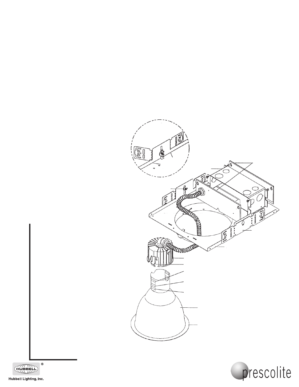
Plaster Frame
Reflector
Heatsink
CAUTION: DO NOT ATTEMPT TO MODIFY OR REWIRE FACTORY-INSTALLED WIRING ON THE FIXTURE. SAFETY AND PROPER
OPERATION OF THE FIXTURE DEPEND ON THE INTEGRITY OF THE WIRING.
1. Bend brackets as shown in Detail “A”.
Install the fixture in the ceiling using
mounting channel or bar (by others)
placed in the adjustable mounting
brackets. Mount the fixture in the ceiling
so that the weight of the fixture is
supported by the mounting channel or bar
and/or hanger wires secured to the
building structure.
2. Adjust the fixture so the bottom of the
plaster frame is flush with the finished
ceiling line and in alignment with adjacent
fixtures. Secure mounting brackets by
tightening wing nuts on either side of the
fixture.
3. CAUTION: CONDUIT CONNECTORS
MAY INTERFERE WITH COMPONETS
HOUSED IN THE J-BOX. CHECK
CLEARANCES BEFORE REMOVING
KNOCKOUTS. Attach the conduit in con-
formance with the National Electric Code.
4. Remove J-Box cover plate. Remove
appropriate knockout and assemble
appropriate connector for the supply wire
used. Connect ground wires to green
ground leads. Connect white (common) to
white (leads). Connect power supply (line)
to black lead(s). Reinstall J-Box cover.
WARNING: DO NOT pinch wires
between J-Box/ballast cover and J-Box.
Consult a Qualified Electrician for all
other options that require other wiring
configurations.
5. Install the reflector after all ceiling installa-
tion and finishing work is complete. Insert
ends of heatsink spring into reflector neck
in alignment with slots then push heatsink
down until desired position is obtained.
Push reflector into the plaster frame until
the reflector flange is flush with ceiling.
6. Install the proper lamp (by others).
Wing Nut
DETAIL “A”
Use this Position for 42 Watt Triple Tube Lamp
and 26 Watt Quad Tube Lamp
Bend Brackets in
Line with Marks
on Flange
J-Box Covers
J-Box
Heatsink Spring
Mounting
Bracket
Use this Position for 26 Watt Triple Tube Lamp
and 13 Watt Quad Tube Lamp
Use this Position for 32 Watt Triple Tube Lamp
and 18 Watt Quad Tube Lamp
Reflector Flange
IMPORTANT SAFETY INFORMATION. READ AND FOLLOW ALL SAFETY INSTRUCTIONS. Follow label information
and instructions concerning Wet or Damp Locations, installation near combustible materials, insulation, building materials,
and proper lamping. Do not install in areas subject to combustible vapors or gases. Before wiring to power supply and
during servicing or relamping, turn off power at fuse or circuit breaker. All servicing or relamping must be performed by
qualified service personnel. Product must be grounded to avoid potential electric shock or other potential hazard.
Product must be mounted in locations and at heights and in a manner consistent with its intended use, and in
compliance with the National Electrical Code and local codes. The use of accessory equipment not recommended by
the manufacturer or installed contrary to instructions may cause an unsafe condition. Do not block light emanating from
product in whole or part, as this may cause an unsafe condition. Do not allow items such as drapes, curtains, screens or
the like to come into contact with the product or to block light from the product, as this may cause an unsafe condition.
701 Millennium Boulevard • Greenville, SC 29607
With representatives offices in principal cities throughout North America.
Copyright 2007, 02/07 revision, All Rights Reserved - Printed in U.S.A.