Prescolite CFR6EB User Manual
Instruction sheet, Installation instructions cat. no. cfr6eb, Prs.4tec
Instruction
Sheet
www.prescolite.com
•
Prescolite
TollFree
Technical
Support
1.888.PRS.4TEC
•
Hours:
8am
- 5pm
ET
701 Millennium Blvd., • Greenville, SC 29607
With representatives offices in principal cities throughout North America.
Copyright 2009, 10/29 revision, All Rights Reserved - Printed in U.S.A.
Part No. . . . . . . . . . . . . . . . . . . . . . . . . . . . . 05935800
Instruction
Sheet
INSTALLATION INSTRUCTIONS
CAT. NO. CFR6EB
Reflector
CAUTION: DO NOT ATTEMPT TO MODIFY OR REWIRE FACTORY-INSTALLED WIRING ON THE FIXTURE. SAFETY AND PROPER
OPERATION OF THE FIXTURE DEPEND ON THE INTEGRITY OF THE WIRING.
WARNING- This product contains chemicals known to the State of California to cause cancer, birth defects and/or other reproductive
harm. Thoroughly wash hands after installing, handling, cleaning, or otherwise touching this product.
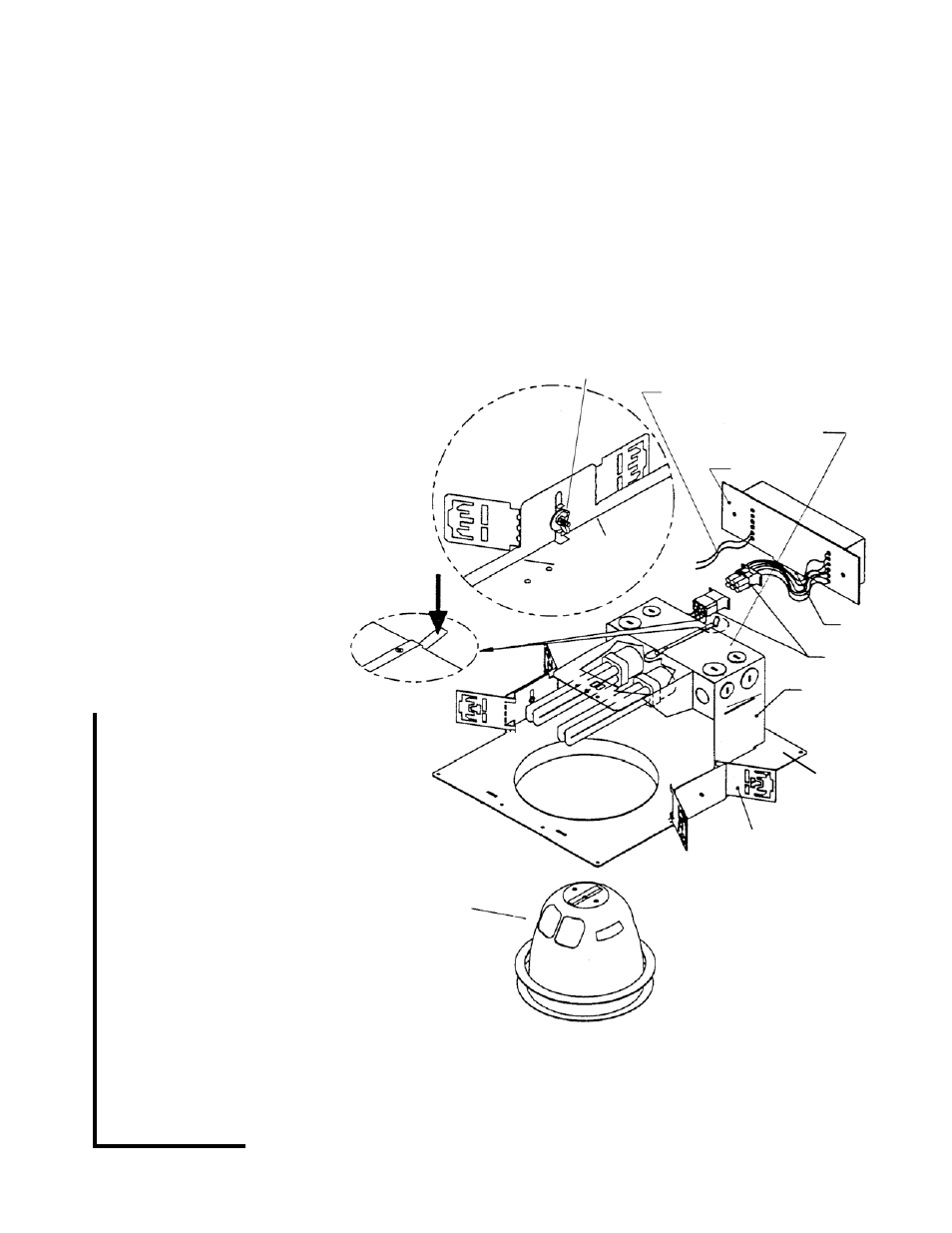
1. Bend brackets as shown in Detail “A”. Install
the fixture in the ceiling using mounting chan-
nel or bar (by others) placed in the adjustable
mounting brackets. Mount the fixture in
the ceiling so that the weight of the fixture is
supported by the mounting channel or bar
and/or hanger wires secured to the building
structure.
2. Adjust the fixture so the bottom of the plaster
flange is flush with the finished ceiling line
and in alignment with adjacent fixtures. Secure
mounting brackets by tightening wing nuts on
either side of the fixture.
3. Remove J-Box cover plate. Remove appropriate
knockout and assemble appropriate connec-
tor for the supply wire used. Connect ground
wires to green ground leads. Connect white
(common) to white (leads). Connect power sup-
ply (line) to black lead(s). Reinstall J-Box cover.
WARNING: DO NOT pinch wires
between J-Box/ballast cover and
J-Box. Consult a Qualified Electrician
for all other options that require other
wiring configurations.
4. Connect the Mate-N-Lock Connectors
from the ballast to the connectors
from the fixture. Push all connectors and
splices into the J-Box.
5. Install the ballast assembly by positioning
the tab on the ballast mounting plate in the
slot on the J-Box bottom plate. Secure bal-
last assembly by snapping plate under J-Box
Spring and bending spring down (See Detail
“B”). WARNING: Do Not pinch Wires
between Ballast and J-Box or between
J-Box and covers!
6. After all ceiling installation and finishing work
is complete. Install the reflector.
7. Install the proper lamps (by others).
Wing Nut
Tab
Press
Spring
Down on
Both Sides
of the
J-Box
DETAIL B
DETAIL “A”
Ballast
Assembly
Bend Brackets in
Line with Marks
on Flange
Dimming Control Leads
where applicable
For Wall Wash Units:
This Side Closest to
Wall to be illumi-
nated
Mate-N-Lock
Connectors
where appli-
cable
J-Box
Adjustable
Mounting
Bracket
IMPORTANT: FOR WALL WASH UNITS ONLY-FIXTURE MUST BE INSTALLED WITH J-BOX CLOSEST TO THE WALL TO BE
ILLUMINATED.
IMPORTANT SAFETY INFORMATION. READ AND FOLLOW ALL SAFETY INSTRUCTIONS. Follow label information and
instructions concerning Wet or Damp Locations, installation near combustible materials, insulation, building materials, and
proper lamping. Do not install in areas subject to combustible vapors or gases. Before wiring to power supply and during
servicing or relamping, turn off power at fuse or circuit breaker. All servicing or relamping must be performed by
qualified service personnel. Product must be grounded to avoid potential electric shock or other poten-
tial hazard. Product must be mounted in locations and at heights and in a manner consistent with its
intended use, and in compliance with the National Electrical Code and local codes. The use of accessory
equipment not recommended by the manufacturer or installed contrary to instructions may cause an unsafe condition. Do
not block light emanating from product in whole or part, as this may cause an unsafe condition. Do not allow items such
as drapes, curtains, screens or the like to come into contact with the product or to block light from the product, as this may
cause an unsafe condition.
When Wall
Wash Trim is
used, This End
of fixture must
be positioned
towards the
wall.
NOTE: Brackets are
supplied flat. To
insure proper align-
ment, bend brackets
in line with marks on
flange as shown in
detail “A”.