Prescolite D4 User Manual
Ins tru ctio n s he et, Installation instructions cat. no. d4
Ins
tru
ctio
nS
he
et
w
w
w
.p
r
e
s
c
o
li
te
.c
o
m
•P
res
co
lite
To
llF
ree
Te
ch
nic
al
Su
pp
ort
1.8
88
.P
RS
.4T
EC
•
Ho
urs
:8
am
-5
pm
ET
701 Millennium Boulevard • Greenville, SC 29607
With representatives offices in principal cities throughout North America.
Copyright 2007, 06/07, All Rights Reserved - Printed in U.S.A.
Part No. . . . . . . . . . . . . . . . . . . . . . . . . . . . . . . . .93001353
Ins
tru
ctio
nS
he
et
INSTALLATION INSTRUCTIONS
CAT. NO. D4
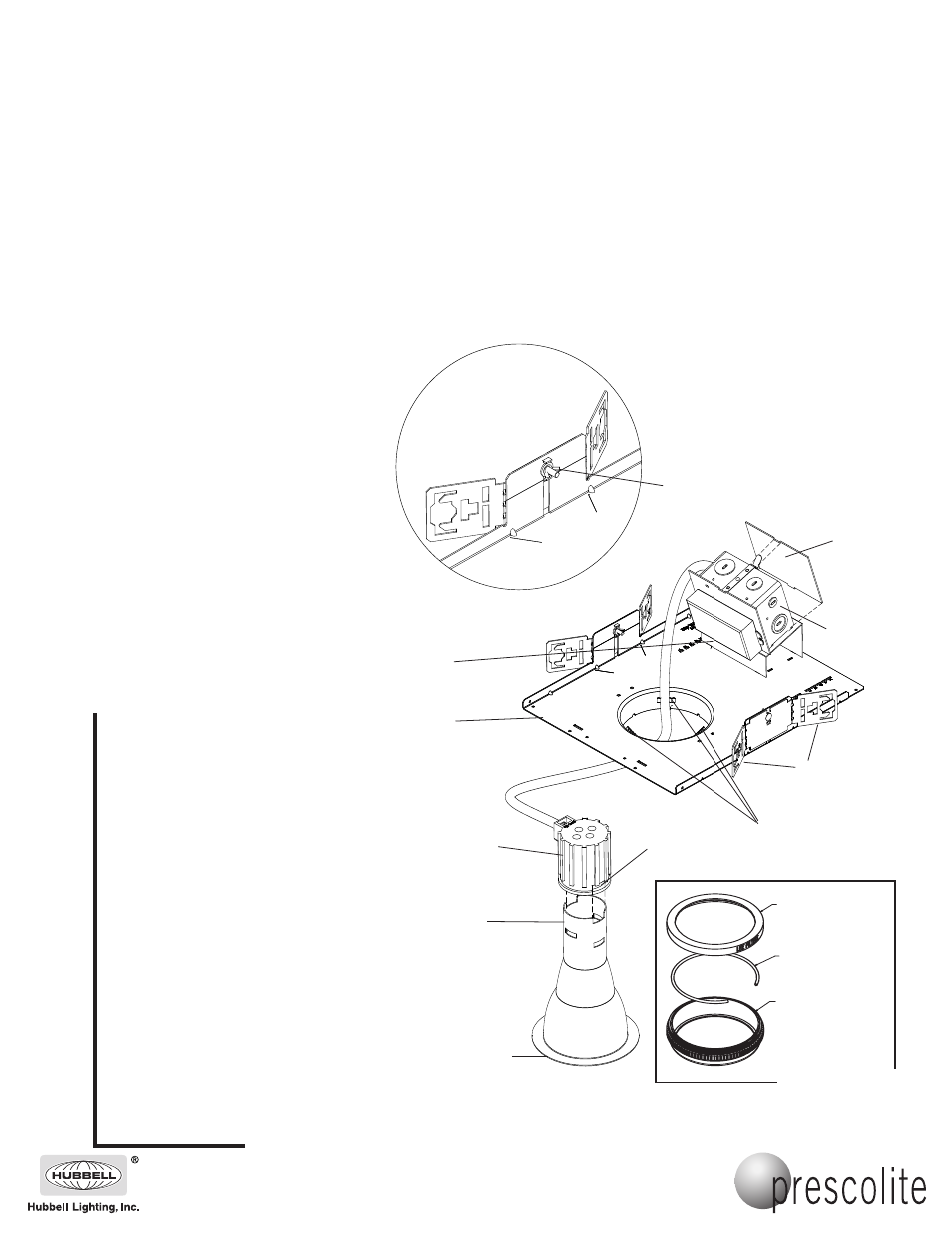
Reflector
Adjustable
Mounting
Bracket
CAUTION: DO NOT ATTEMPT TO MODIFY OR REWIRE FACTORY-INSTALLED WIRING ON THE FIXTURE. SAFETY AND PROPER
OPERATION OF THE FIXTURE DEPEND ON THE INTEGRITY OF THE WIRING.
SAVE THESE INSTRUCTIONS.
1. Bend brackets as shown in Detail “A”. Install the
fixture in the ceiling using mounting channels or bar
hangers (B6, B24, or by others) placed in the
adjustable mounting brackets. Mount the fixture in
the ceiling so that the weight of the fixture is
supported by the mounting channel or bar and/or
hanger wires secured to the building structure.
2. Adjust the fixture so the bottom edge of the plaster
flange opening is flush with the finished ceiling line
and in alignment with adjacent fixtures. Secure
mounting brackets by tightening wing nuts on either
side of the fixture.
3. Remove and discard the wire twist around the
J-Box covers. Remove J-Box cover plate.
Remove appropriate knockout and assemble
certified conduit connector for the supply wire used.
Connect supply ground wire to fixture ground wire.
Connect common supply wire to white fixture wire.
Connect 120V or 277V supply wire to the respec-
tive 120V or 277V fixture wire. Use certified wire
nuts. Reinstall J-Box cover.
WARNING: DO NOT pinch wires between
J-Box/ballast cover and J-Box. Consult a
Qualified Electrician for all other options that
require other wiring configurations.
4. Install reflector after all ceiling installation and
finishing work is complete.
Insert sides of heatsink spring into reflector neck
clearance slots, then twist heatsink and push down
until desired position on the reflector is obtained.
Align heatsink spring with appropriate reflector
slots. Heatsink will lock into place, but may be
readjusted by twisting and sliding the heatsink into
another position. Do NOT use the reflector neck
clearance slots as a final installation position for the
heatsink.
5. Push reflector into the plaster flange until the
reflector is flush against the ceiling.
6. Install the proper lamps (by others).
7. For housing CAT. NO. D4MR, install a lamp marked
“Suitable for use in open luminaires” unless used in
combination with Prescolite CAT. NO. 2MLH.
8. To install the accessory CAT. NO. 2MLH, first have
the reflector installed in the housing. Separate the
halves of 2MLH by twisting them apart. Remove
the lens retainer wire. Place the maximum quantity
of two (2) optical accessories and the MR16 lamp
into the bottom half of 2MLH. Replace the lens
retainer wire over the edge of the MR16 lamp.
Combine the halves of 2MLH by twisting them
together. Finally, insert the MR16 lamp pins into
the Leviton MR16 lampholder. Replace removable
parts after servicing.
Wing Nut
NOTE: Brackets are
supplied flat. To ensure
proper alignment, bend
brackets in line with
marks on flange as
shown in Detail A.
DETAIL A
2MLH
J-Box
Transformer/
Ballast
Plate
Bend Brackets in
Line with Marks
on Flange.
NOTE: Remove (3) Grip
Clip Springs before
installing a Wallwash
Trim.
Heatsink
Plaster
Flange
J-Box
Cover
IMPORTANT SAFETY INFORMATION. READ AND FOLLOW ALL SAFETY INSTRUCTIONS. Follow label information
and instructions concerning Wet or Damp Locations, installation near combustible materials, insulation, building materials,
and proper lamping. Do not install in areas subject to combustible vapors or gases. Before wiring to power supply and
during servicing or relamping, turn off power at fuse or circuit breaker. All servicing or relamping must be performed by
qualified service personnel. Product must be grounded to avoid potential electric shock or other potential hazard.
Product must be mounted in locations and at heights and in a manner consistent with its intended use, and in
compliance with the National Electrical Code and local codes. The use of accessory equipment not recommended by
the manufacturer or installed contrary to instructions may cause an unsafe condition. Do not block light emanating from
product in whole or part, as this may cause an unsafe condition. Do not allow items such as drapes, curtains, screens or
the like to come into contact with the product or to block light from the product, as this may cause an unsafe condition.
See Label for
Lamp Positioning:
Heatsink
Spring
Media Holder Bottom
Lens Retainer Ring
Media Holder Top