Prescolite 93047LED Retrofit Kit User Manual
Instruction sheet, Prs.4tec
www.prescolite.com
•
Prescolite
TollFree
Technical
Support
1.888.PRS.4TEC
•
Hours:
8am
- 5pm
ET
701 Millennium Blvd., • Greenville, SC 29607
With representatives offices in principal cities throughout North America.
Copyright 2011, 5/17/11 revision, All Rights Reserved - Printed in U.S.A.
Part No...................................................... 93036385
Instruction
Sheet
INSTALLATION INSTRUCTIONS
93047 LED Retrofit Kit
IMPORTANT SAFETY INFORMATION. READ AND FOLLOW ALL SAFETY INSTRUCTIONS. Follow label information and instructions con-
cerning Wet or Damp Locations, installation near combustible materials, insulation, building materials, and proper lamping. Do not install in
areas subject to combustible vapors or gases. Before wiring to power supply and during servicing or relamping, turn off power at fuse or
circuit breaker. All installation servicing or relamping must be performed by qualified service personnel. Product must
be grounded to avoid potential electric shock or other potential hazard. Product must be mounted in locations and
at heights and in a manner consistent with its intended use, and in compliance with the National Electrical Code
and local codes. The use of accessory equipment not recommended by the manufacturer or installed contrary to instructions may cause
an unsafe condition. Do not block light emanating from product in whole or part, as this may cause an unsafe condition. Do not allow items
such as drapes, curtains, screens or the like to come into contact with the product or to block light from the product, as this may cause an
unsafe condition.
WARNING- This product contains chemicals known to the State of California to cause cancer, birth defects and/or
other reproductive harm. Thoroughly wash hands after installing, handling, cleaning, or otherwise touching this
product.
1. Remove existing faceplate
2. Remove the ballast cover.
3. Disconnect the power leads for the ballast.
4. Remove the ballast, ballast bracket, capacitor, and igniter.
5. Remove the socket, socket bracket, upper reflector, and
spacers.
6. Disconnect the leads to the thermal protector
7. Clean out the housing
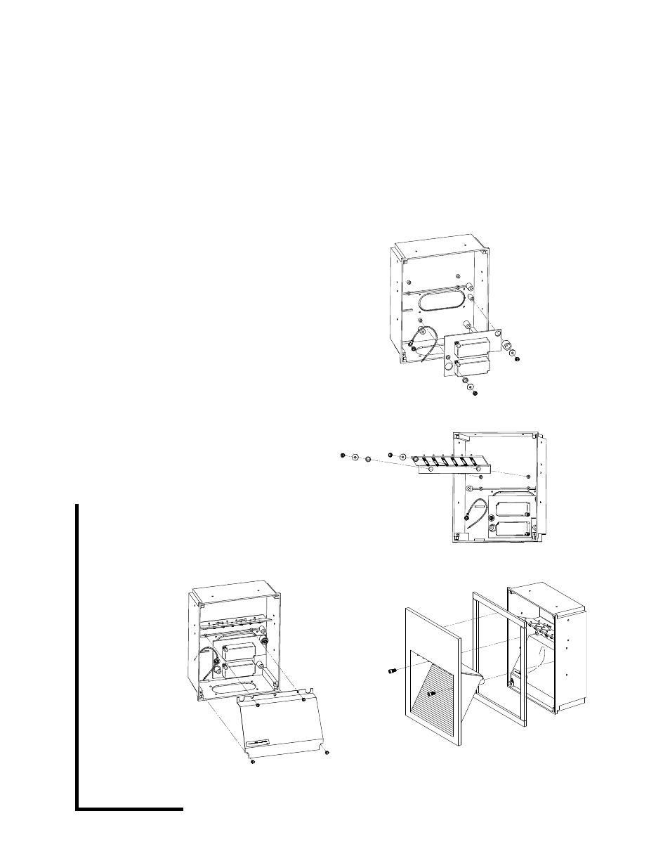
8. Install the plate with the two LED drivers (supplied) with the
spacers, washers, and screws. See figure 1.
9. Install ground wire.
10. Install the LED array bracket (supplied) with the spacers,
washers, and screws. See figure 2.
11. Connect the LED array and driver assemblies.
12. Route the red and black LED wires against the back of the
housing next to the big bosses on both sides of the housing
so they won’t pinch when the ballast cover is installed.
13. Connect the power to the two drivers.
14. Install the new ballast cover (supplied). See figure 3.
15. Apply the new gasket to the faceplate. Remove the protective
film from the faceplate reflector.
16. Install the new faceplate with the socket head screws. See
figure 4.
FIGURE 1
FIGURE 3
FIGURE 1
FIGURE 2
FIGURE 3
FIGURE 4
CAUTION: DO NOT ATTEMPT TO MODIFY OR REWIRE FACTORY-INSTALLED WIRING ON THE FIXTURE. SAFETY AND PROPER
OPERATION OF THE FIXTURE DEPEND ON THE INTEGRITY OF THE WIRING.
KEEP THESE INSTALLATION INSTRUCTIONS